Hydraulic fluid pump for a motor vehicle brake system, comprising an eccentric drive

A technology of automobile braking system and hydraulic fluid, which is applied in the direction of brakes, liquid variable capacity machinery, pumps, etc., to achieve the effect of easy assembly and low cost

Inactive Publication Date: 2013-06-19
ROBERT BOSCH GMBH
View PDF0 Cites 0 Cited by
  • Summary
  • Abstract
  • Description
  • Claims
  • Application Information

AI Technical Summary

Problems solved by technology

Due to this linear relationship, although the hydraulic load torque on known hydraulic fluid pumps can be well set by simply adjusting the current strength, such hydraulic fluid pumps are not optimal in all parts of the operating range. Work

Method used


Image

  • Hydraulic fluid pump for a motor vehicle brake system, comprising an eccentric drive
  • Hydraulic fluid pump for a motor vehicle brake system, comprising an eccentric drive
  • Hydraulic fluid pump for a motor vehicle brake system, comprising an eccentric drive

Examples


Embodiment Construction

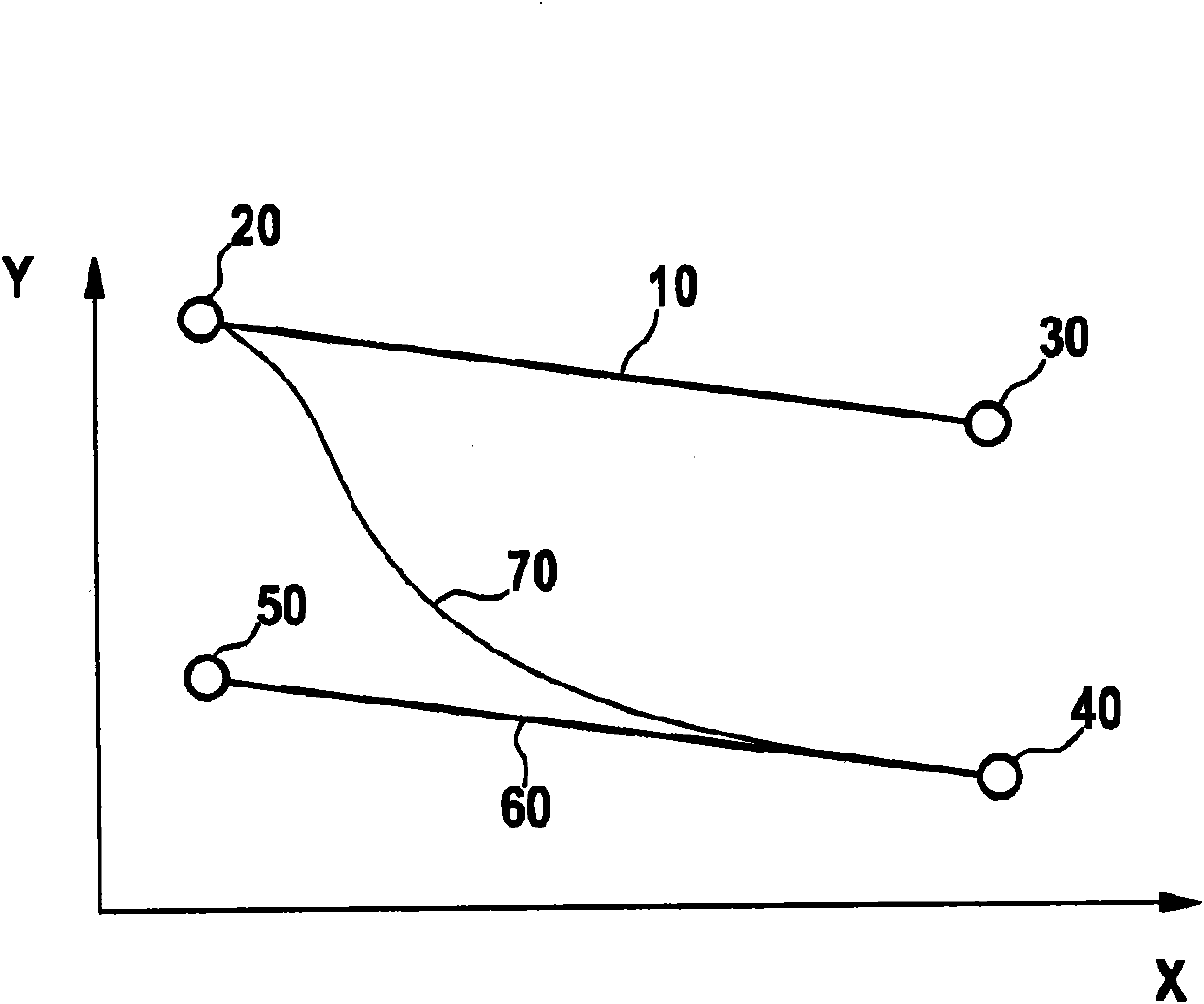
[0032] exist figure 1 In, as already explained above, it is shown how the solution according to the invention can suitably provide a delivery rate of the delivery device of the hydraulic fluid pump on the vehicle brake system which varies depending on the magnitude of the hydraulic back pressure. At this point, regarding the figure 1 The description can be found in the description above.

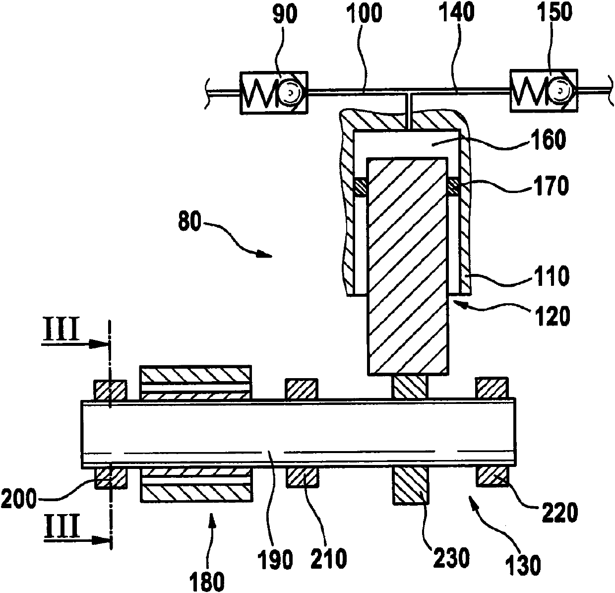
[0033] exist figure 2 A hydraulic fluid pump 80 is shown in , its main components include an inlet valve 150, an inlet pipe 140, a cylinder 110 with a piston 120 located therein, a corresponding eccentric gear 130, an outlet pipe 100 and an outlet valve 90 . Here, the inlet valve 150, the inlet line 140 and the outlet line 100 together with the outlet valve 90 are fluidically connected to the compression chamber 160 formed by the cylinder 110 and the piston 120, so that hydraulic fluid (not shown) passes through the piston The movement of 120 in cylinder 110 is sucked into and outputted f...


PUM


Abstract

Disclosed is a hydraulic fluid pump (80) for a motor vehicle brake system, comprising delivery means (110, 120) for delivering hydraulic fluid against a hydraulic counter-pressure prevailing in one part of the vehicle brake system (140, 150). Said hydraulic fluid pump (80) further comprises means (270), preferably an elastomer component in the motor shaft bearing (200, 220), for modifying the volume delivered by the delivery means (110, 120) in accordance with the level of the hydraulic counter-pressure.

Description

technical field [0001] The invention relates to a hydraulic fluid pump for a vehicle braking system comprising delivery means for delivering hydraulic fluid against a hydraulic back pressure present in a part of the vehicle braking system. Furthermore, the invention also relates to a vehicle brake system comprising such a hydraulic fluid pump. Background technique [0002] Hydraulic fluid pumps for vehicle braking systems are known, in which hydraulic fluid pumps are used for conveying hydraulic fluid or brake fluid in the vehicle braking system, in particular for returning brake fluid and / or To actively increase the brake pressure, reciprocating piston pumps are used as delivery devices. These reciprocating piston pumps are also referred to as pump elements. [0003] These pump elements are usually driven by an electric motor with an eccentric mounted on the drive shaft. As an alternative, cam drives or the like can also be used. Depending on the eccentricity of the ecc...

Claims


Application Information

Patent Timeline
Patent Type & Authority Patents(China)
IPC IPC(8): B60T8/40F04B49/12
CPCF04B49/08F04B49/123F04B49/12B60T8/4031F04B1/04
Inventor C·多贝斯丘埃兹W·奎兰特
Owner ROBERT BOSCH GMBH
Why Eureka
Try Eureka