Flexible control loop of hydraulic cylinder and engineering mechanical equipment

A telescopic control and hydraulic cylinder technology, which is applied in mechanical equipment, fluid pressure actuators, servo motor components, etc., can solve problems such as reduced system reliability and inability to insert pins

Active Publication Date: 2012-05-02
ZOOMLION HEAVY IND CO LTD
View PDF6 Cites 12 Cited by
  • Summary
  • Abstract
  • Description
  • Claims
  • Application Information

AI Technical Summary

Problems solved by technology

[0006] Specifically, the current hydraulic expansion mechanism has the following disadvantages when the bolt mechanism is in action: when the bolt mechanism is in motion, assuming that the pressure of the hydraulic oil in the central channel is P, and the outer diameter of the core tube of the central channel is d, the core tube and the The force on its end face is: F=(π×d 2 ×P) / 4, it can be seen that F is proportional to the pressure P and the outer diameter of the core tube d
When the hydraulic cylinder is actually stretching, when the hydraulic cylinder stretches to the predetermined position (the cylinder pin or arm pin has been aligned with the pin hole), and when the cylinder pin or arm pin is ready to be extended, the force F will push the cylinder to extend at the same time. Therefore, the pin hole position where the cylinder pin and the arm pin are aligned fails, and the pin cannot be inserted
The current telescopic system often has the above-mentioned failures when the latch mechanism operates, resulting in reduced system reliability

Method used


Image

  • Flexible control loop of hydraulic cylinder and engineering mechanical equipment
  • Flexible control loop of hydraulic cylinder and engineering mechanical equipment
  • Flexible control loop of hydraulic cylinder and engineering mechanical equipment

Examples


Embodiment Construction

[0030] The specific embodiments of the present invention will be described in detail below in conjunction with the accompanying drawings. It should be understood that the specific embodiments described here are only used to illustrate and explain the present invention, and the protection scope of the present invention is not limited to the following specific embodiments. .

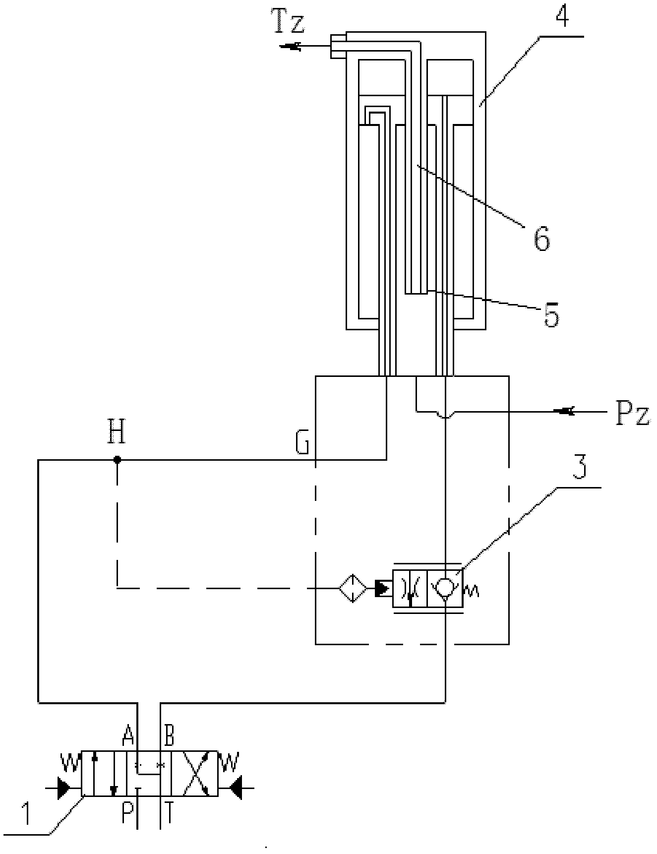
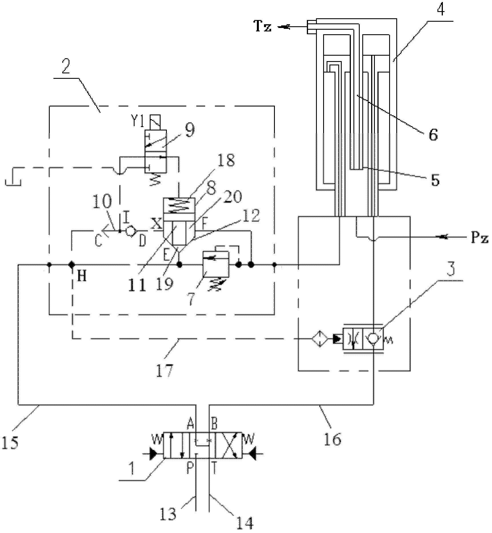
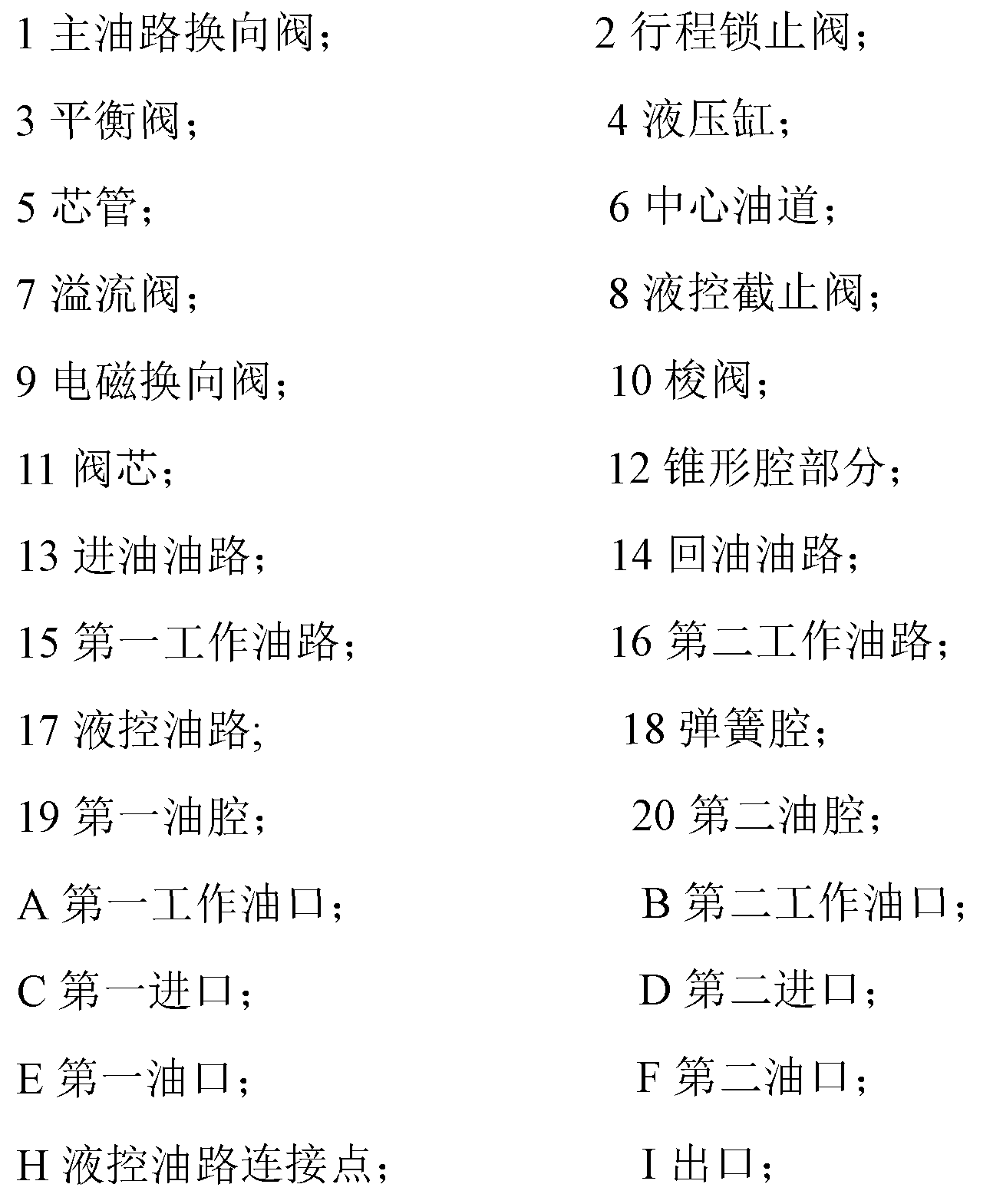
[0031] First of all, it needs to be explained that the telescoping control circuit of the hydraulic cylinder of the present invention belongs to the hydraulic field, and its substantive technical concept lies in the hydraulic connection relationship, not in the specific mechanical structure. For example, as far as the stroke lock valve used in the hydraulic cylinder expansion and contraction control circuit of the present invention is concerned, its composition should be understood from a broad hydraulic principle, and should not be limited to the specific form shown in the accompanying drawings, that is, t...


PUM


Abstract

The invention relates to a flexible control loop of a hydraulic cylinder. The flexible control loop of the hydraulic cylinder comprises an oil inlet path (13), an oil return path (14), a first working oil path (15), a second working oil path (16) and a main oil path steering valve (1) for realizing flexible control over the hydraulic cylinder (4), wherein the first working oil path (15) and the second working oil path (16) are respectively connected to a rod cavity and a rodless cavity of the hydraulic cylinder (4); and a switching valve for controlling the first working path (15) to open and close is connected to the first working oil path (15). Besides, the invention also provides engineering mechanical equipment provided with the flexible control loop of the hydraulic cylinder. According to the flexible control loop of hydraulic cylinder and the engineering mechanical equipment disclosed by the invention, by arranging the switching valve on the first control oil path, the first control oil path is controlled to open and close as required, a stroke locking function for preventing a stretching member of the hydraulic cylinder from continuously extending due to accidental means is effectively realized, and therefore working reliability of the hydraulic cylinder is ensured.

Description

technical field [0001] The invention relates to a hydraulic control system of a hydraulic cylinder, in particular to a telescopic control circuit of a hydraulic cylinder. In addition, the present invention also relates to a construction machinery equipment provided with the telescoping control circuit of the hydraulic cylinder. Background technique [0002] Hydraulic telescopic mechanisms on construction machinery and other mechanical equipment mostly use hydraulic cylinders as telescopic drive devices. [0003] For example, as far as hydraulic cranes are concerned, especially large-tonnage or super-large-tonnage cranes are mostly single-cylinder multi-section boom telescopic structures, in which oil is supplied to the hydraulic cylinder through the main oil circuit reversing valve in the telescopic control circuit of the hydraulic cylinder to control Its telescopic movement, the extension length of the hydraulic cylinder can be measured by the displacement sensor. Usually...

Claims


Application Information

Patent Timeline
Patent Type & Authority Applications(China)
IPC IPC(8): F15B15/16F15B15/26F15B13/04
Inventor 詹纯新刘权张建军李英智胡廷江李怀福
Owner ZOOMLION HEAVY IND CO LTD
Why Eureka
Try Eureka