Cutting device and method for setting up and testing the operation preparation of cutting device

A cutting equipment and technology for cutting tubes, which are applied in the fields of application, tobacco, and paper cigarette manufacturing, and can solve problems such as uncertainty or avoiding collision hazards

Inactive Publication Date: 2015-04-29
HAUNI MASCHINENBAU AG
View PDF6 Cites 0 Cited by
  • Summary
  • Abstract
  • Description
  • Claims
  • Application Information

AI Technical Summary

Problems solved by technology

The known synchronous control with a rotary encoder (Drehgeber) for establishing synchronization on the basis of the encountered cutting positions cannot determine or avoid a collision risk when there are assembly errors, adjustment errors and / or or calibration error when

Method used


Image

  • Cutting device and method for setting up and testing the operation preparation of cutting device
  • Cutting device and method for setting up and testing the operation preparation of cutting device
  • Cutting device and method for setting up and testing the operation preparation of cutting device

Examples


Embodiment Construction

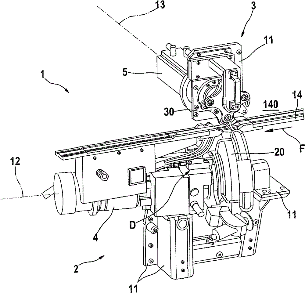
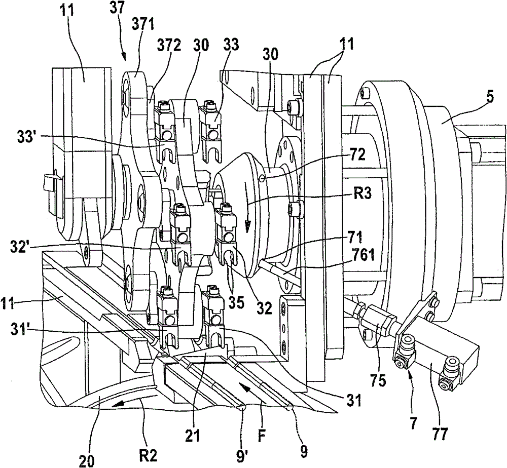
[0026] The cutting device according to the invention is designed as a machine in the tobacco processing industry for cutting at least one conveyed strand into a plurality of rod-shaped products. In particular, cigarettes are processed from cigarette sticks, ie from sections of double-length tobacco strands 9, 9'. The tobacco bundle 9 or 9' is fed continuously and at a constant speed in the conveying direction F. The cigarette sticks 91 or 91' (not shown) are cut (abtrennen) by the cutting device 1 and delivered to an intermediate conveyor (ie a so-called star wheel not shown). Such a spider is known, for example, from DE 10 2004 013 972 A1. Filters are also cut, for example, at the point of the cigarette.

[0027] The cutting device 1 is designed in a special manner according to the invention. The method steps according to the invention, in particular for the test run preparation, can be carried out with the cutting device 1 described in the exemplary embodiment, as describ...


PUM


Abstract

The cutting device (1) has a control device (8) aligned and connected with the rotary drives (4,5) of a knife carrier (20) and a tube carrier for controlling, such that it fixes the knife carrier and the tube carrier for setting up and testing the operational readiness of the cutting device in a predetermined base-turn position assigned to the blade position and in a predetermined base-turn position assigned to a tube position. An independent claim is also included for a method for setting and examining operational status of a cutting device.

Description

technical field [0001] The invention relates to a method for cutting at least one transported strand (Strang) into a plurality of rods Cutting plant for the tobacco processing industry of products, especially cigarettes, filters or the like, comprising a machine base frame (Maschinengrundgestell), a knife device (which is driven by rotation, carrying at least one radial knife, with The tool holder of the axis of rotation is formed), the pipe device (Tubeneinrichtung) (which is formed by a pipe holder which is driven by rotation, carries at least one cutting pipe, and has an axis of rotation), the direct rotary drive of the tool holder and the pipe holder (which Formed by a frame-mounted (gestellfest) electric motor) and an electronic control unit, which is connected to the rotary drive for control and controls its synchronous operation. The two support axes of rotation are located transversely to each other and in a defined orientation based on the machine base frame for the...

Claims


Application Information

Patent Timeline
Patent Type & Authority Patents(China)
IPC IPC(8): A24C5/28A24C5/31
CPCA24C5/28
Inventor F·格罗索斯C·拉克曼B·布林克曼
Owner HAUNI MASCHINENBAU AG
Why Eureka
Try Eureka