
Micro-dose flow regulator

A flow regulator and micro-dosing technology, which is applied to hypodermic injection devices and other directions, can solve the problems of complex structure, unsuitability, and large residual amount of medicinal liquid, so as to reduce the workload, reduce the residual amount of medicinal liquid, and accurately adjust the flow rate. Effect

Active Publication Date: 2012-07-04
威海威高医用材料有限公司
View PDF0 Cites 3 Cited by
  • Summary
  • Abstract
  • Description
  • Claims
  • Application Information

AI Technical Summary

Problems solved by technology

However, its structure is complex, especially because there is a circle of deep to shallow grooves on the rotating disk, resulting in a large amount of liquid medicine residue
Not suitable for flow control of small flow infusion of some special drugs

Method used


Image

  • Micro-dose flow regulator
  • Micro-dose flow regulator
  • Micro-dose flow regulator

Examples


Embodiment Construction

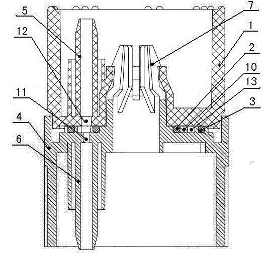
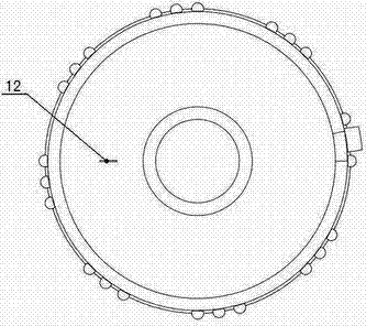
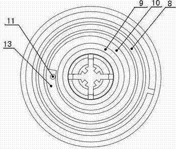
[0015] from figure 1 It can be seen from the figure that a micro-dosage flow regulator includes an upper casing 1 and a lower casing 4, the upper casing 1 is provided with a liquid inlet conduit connector 5, and the lower casing 4 is provided with a liquid outlet conduit connector 6 , The upper housing 1 and the lower housing 4 are connected to each other through a central buckle 7, and can be rotated relative to each other. The micro-dosage flow regulator is assembled between the dripping funnel of the infusion set and the filter, the liquid enters through the conduit from the liquid inlet conduit joint 5 of the upper housing 1, and flows out from the liquid outlet conduit joint 6 of the lower housing 4 to connect the conduit. The specific composition and connection of the center buckle 7 belong to the prior art, and will not be repeated here.

[0016] The feature of the present invention is: the bottom end surface of said upper casing 1 is radially provided with an elongate...


PUM


Abstract

The invention relates to a micro-dose flow regulator. The micro-dose flow regulator comprises an upper shell and a lower shell, wherein a liquid inlet conduit joint is arranged in the upper shell; a liquid outlet conduit joint is arranged in the lower shell; the upper shell is connected with the lower shell through a central fastener; a lathy through hole communicated with the liquid inlet conduit joint is radially formed on the bottom end face of the upper shell; the upper end face of the lower shell is contacted with the bottom end face of the upper shell; a reducing transfusion groove fromnarrow to wide is formed on the upper end face of the lower shell opposite to the lathy through hole on the bottom end face of the upper shell; a liquid outlet round through hole communicated with the liquid outlet conduit joint is formed on the widest part of the reducing transfusion groove; the lathy through hole of the upper shell, the reducing transfusion groove on the upper end face of the lower shell and the liquid outlet round through hole form an interconnected transfusion channel; and the width of the reducing transfusion groove opposite to the lathy through hole is regulated by relatively rotating the upper shell and the lower shell, so that the accurate and micro-dose adjustment of the transfusion flow is realized. The micro-dose flow regulator has the characteristics of reasonable structure, and simple and convenient operation and use.

Description

technical field [0001] The invention relates to a flow regulating device for a medical infusion set, in particular to a micro-dosage flow regulator for an infusion set. Background technique [0002] As we know, the flow regulator of the traditional infusion set is installed outside the infusion catheter, and the pressure wheel is used to press the catheter to realize the flow adjustment of the infusion set. The flow adjustment accuracy of the flow regulator with this structure is low, and the flow rate cannot be measured. The medical staff can only estimate the flow rate based on the number of drops in the drop bucket based on experience, which increases the workload of the medical staff. It is difficult for the above-mentioned flow regulator to adjust the flow rate. Effective control. At present, there are also micro-dosage flow regulators, such as the Chinese invention patent precision analgesic infusion set with the patent number ZL02135801X, which discloses a micro-dosa...

Claims


Application Information

Patent Timeline
Patent Type & Authority Patents(China)
IPC IPC(8): A61M5/175
Inventor 刘灿伟吴传明孙本涛宋文武
Owner 威海威高医用材料有限公司
Learn More