Crank arm type flying cotton removing device

A clearing device, articulating arm technology, applied in textiles and papermaking, etc., to achieve the effect of improving yarn quality and simple structure

Inactive Publication Date: 2010-12-08
绍兴华裕纺机有限公司
View PDF5 Cites 4 Cited by
  • Summary
  • Abstract
  • Description
  • Claims
  • Application Information

AI Technical Summary

Problems solved by technology

Due to the emergence of compact spinning, such as mechanical compact spinning or negative pressure compact spinning structure, the output top roller is no longer in the original position, and the original straight fly cleaning device can no longer be used to remove fly fiber on the output top roller of compact spinning

Method used


Image

  • Crank arm type flying cotton removing device
  • Crank arm type flying cotton removing device
  • Crank arm type flying cotton removing device

Examples


Embodiment 1

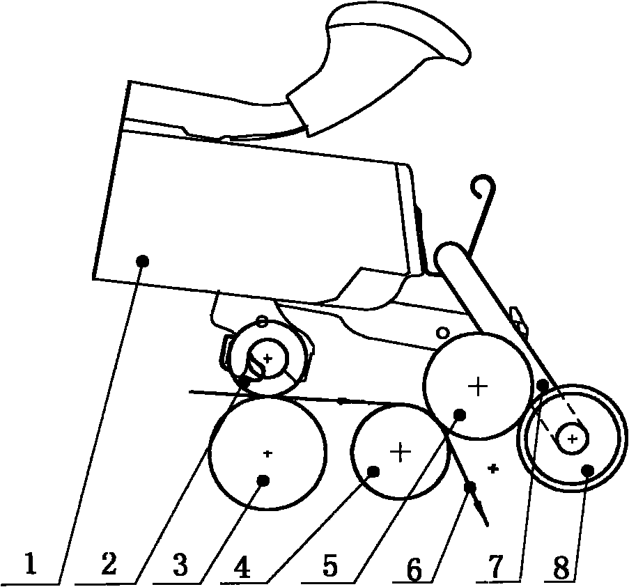
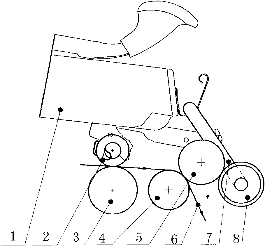
[0022] Embodiment one: see figure 1 , a crank-arm type cleaning device, using the cleaning roller 8 installed on the crank arm 7, the cleaning roller 8 is pressed on the front top roller 5, the middle top roller 2, and the front top roller 5 are installed on the cradle 1, the middle roller 3, and the front roller 4 are installed on the frame, the yarn 6 is twisted after being clamped by the front top roller 5 and the front roller 4, and the cleaning roller 8 is pressed on the front top roller 5 The position where the flying flowers are produced is close to the output end of the yarn. Like this, the cleaning roller 8 is driven to rotate by the front top roller 5, thereby completing the removal of the flying flower fibers attached to the front top roller 5.

[0023] The cleaning roller 8 is connected with the curved arm 7, and the curved arm 7 can place the cleaning roller 8 on the above-mentioned position with magnetic force, gravity or general mechanical force.

[0024] For c...


PUM


Abstract

The invention discloses a crank arm type flying cotton removing device used for ring spinning, in particular compact spinning, and belongs to the technical field of spinning of textile machinery. The device is mainly characterized in that: a flying cotton removing roller is tightly pressed on an output leather roller, and flying cotton fibers stuck on the output leather roller are removed when the output leather roller drives the flying cotton removing roller to rotate. The flying cotton removing roller is fixed on a cradle by a crank arm structure and other available place. The device can clean the flying cotton fibers timely and effectively and improve the yarn quality.

Description

Technical field: [0001] The invention relates to a crank arm type flying flower removing device, in particular, it uses a cleaning roller equipped with a crank arm to remove the flying flower fibers adsorbed on the output top roller. It belongs to the technical field of spinning devices in textile machinery. Background technique: [0002] Before the present invention, in the existing ordinary ring spinning technology, in order to remove the flying fiber attached to the output top rollers, a straight type cleaning device was usually used, that is, two cleaning devices corresponding to a group of output top rollers. The flower rollers are integrated with a straight shaft, and the shaft rests in the steel hook at the front of the cradle, and the two flower rollers are pressed on the output rollers, and the output rollers are driven by the rotation to clean the output rollers. Flying fibers on top rollers. Due to the emergence of compact spinning, such as mechanical compact sp...

Claims


Application Information

Patent Timeline
Patent Type & Authority Applications(China)
IPC IPC(8): D01H11/00
Inventor 刘光容
Owner 绍兴华裕纺机有限公司
Why Eureka
Try Eureka