Methods relating to turbine engine control and operation

A technology of engines and gas turbines, which is applied in the direction of engine components, fuel control of turbines/propulsion devices, machines/engines, etc., and can solve problems such as not being able to determine the temperature in time

Inactive Publication Date: 2010-12-08
GENERAL ELECTRIC CO
View PDF5 Cites 5 Cited by
  • Summary
  • Abstract
  • Description
  • Claims
  • Application Information

AI Technical Summary

Problems solved by technology

Another reason is associated with the timely detection of variable fuel properties (such as heating value) within the fuel supply, which makes it impossible to determine in a timely manner the proper temperature at which the fuel should be delivered to the burner

Method used


Image

  • Methods relating to turbine engine control and operation
  • Methods relating to turbine engine control and operation
  • Methods relating to turbine engine control and operation

Examples


Embodiment Construction

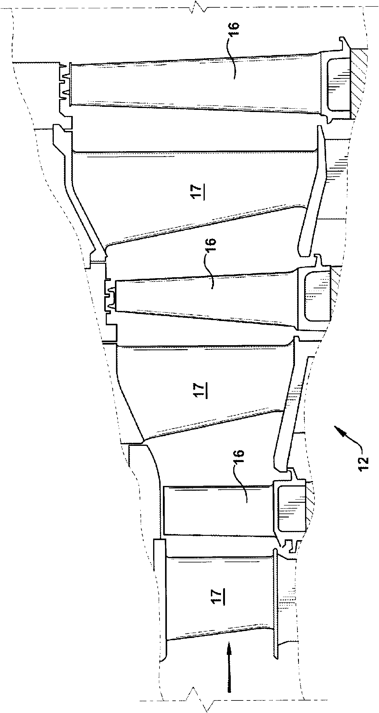
[0031] Referring now to the accompanying drawings, figure 1 A schematic diagram of a gas turbine engine 10 is shown and will be used to describe an exemplary environment in which the present invention may be employed. Those skilled in the art will appreciate that the invention is not limited to this type of use. As stated, the invention may be used in other types of gas turbine engines. In general, gas turbine engines operate by extracting energy from a pressurized hot gas stream produced by burning fuel in a compressed air stream. Such as figure 1 As shown, a gas turbine engine 10 may be configured with an axial compressor 11 mechanically coupled by a common shaft or rotor to a downstream turbine section or turbine 12 with a combustor 13 located between the compressor 11 and the turbine. Between 12.

[0032] figure 2 shows the available figure 1 A view of an exemplary multi-stage axial compressor 11 used in a gas turbine engine. As shown, compressor 11 may include mul...


PUM


Abstract

A method of controlling a combustion turbine engine, wherein the engine includes: a fuel line (50) including a heat exchange portion (52); a heating value meter; a cold leg bypass (76) comprising an alternate fuel line that bypasses the heat exchange portion (52), the cold leg bypass (76) being connected to the fuel line (50) at an upstream fork (62) and at a fuel mixing junction (64), the fuel mixing junction (64) being positioned such that a length of fuel line (50) between it and the inlet to the combustor (30) is short; and valves for controlling the amount of fuel being directed through the heat exchange portion (52); the method comprising: measuring the heating value of the fuel; determining a target fuel temperature range based on the heating value and a target Modified Wobbe Index range; and controlling the fuel that bypasses the heat exchange portion (52) such that the temperature of the fuel is within the target temperature range.

Description

technical field [0001] The present application generally relates to methods, systems and / or apparatus for improving the efficiency and / or operation of gas turbine engines, as used herein and unless specifically stated otherwise, gas turbine engines are meant to include all types of gas or Combustion turbine or rotary engines, including aeroengines, power generating engines and other engines. More particularly, but not by way of limitation, the present application relates to methods, systems and / or apparatus related to fuel delivery methods and systems in gas turbine engines. Background technique [0002] Generally, a gas turbine engine includes a compressor, a combustor, and a turbine. Compressors and turbines generally include rows of blades stacked axially in stages. Each stage includes a row of circumferentially spaced stator blades and a row of rotor blades, the stator blades being fixed, and the rotor blades rotating about a central axis or shaft. In operation, gener...

Claims


Application Information

Patent Timeline
Patent Type & Authority Applications(China)
IPC IPC(8): F02C9/28F02C7/224
CPCF05D2220/75Y02T50/678Y02E50/11F02C6/18F02C7/224Y02E50/10
Inventor T·R·比尔顿D·M·埃里克森D·R·纳拉莫图E·L·麦格拉思胡泰来
Owner GENERAL ELECTRIC CO
Why Eureka
Try Eureka