Apparatus for converting rotary motion into linear motion

A technology of rotary motion and linear motion, applied in transmission devices, friction transmission devices, feeding devices, etc., can solve the problems of high material consumption, extending the diameter of driving shaft rollers and steering shaft rollers, and large steering roller diameters, etc., to achieve Save material and avoid the effect of back reversal

Active Publication Date: 2015-01-21
ENGEL AUSTRIA
View PDF5 Cites 0 Cited by
  • Summary
  • Abstract
  • Description
  • Claims
  • Application Information

AI Technical Summary

Problems solved by technology

The disadvantage of the O setting compared to the Ω setting is the structural length. In the Ω setting, the structural length is only given by the structural length of the linear axis, while in the O setting, the structural length is at least extended by the driving shaft roller and the steering shaft roller. the size of the diameter
Disadvantages of the Ω arrangement compared to the O arrangement are the higher material consumption (two steering axes instead of one), and the so-called reverse rotation of the traction elements in the Ω arrangement (alternating bending), which places higher demands on the material of the traction elements and thus requires a large deflection roller diameter

Method used


Image

  • Apparatus for converting rotary motion into linear motion
  • Apparatus for converting rotary motion into linear motion
  • Apparatus for converting rotary motion into linear motion

Examples


Embodiment Construction

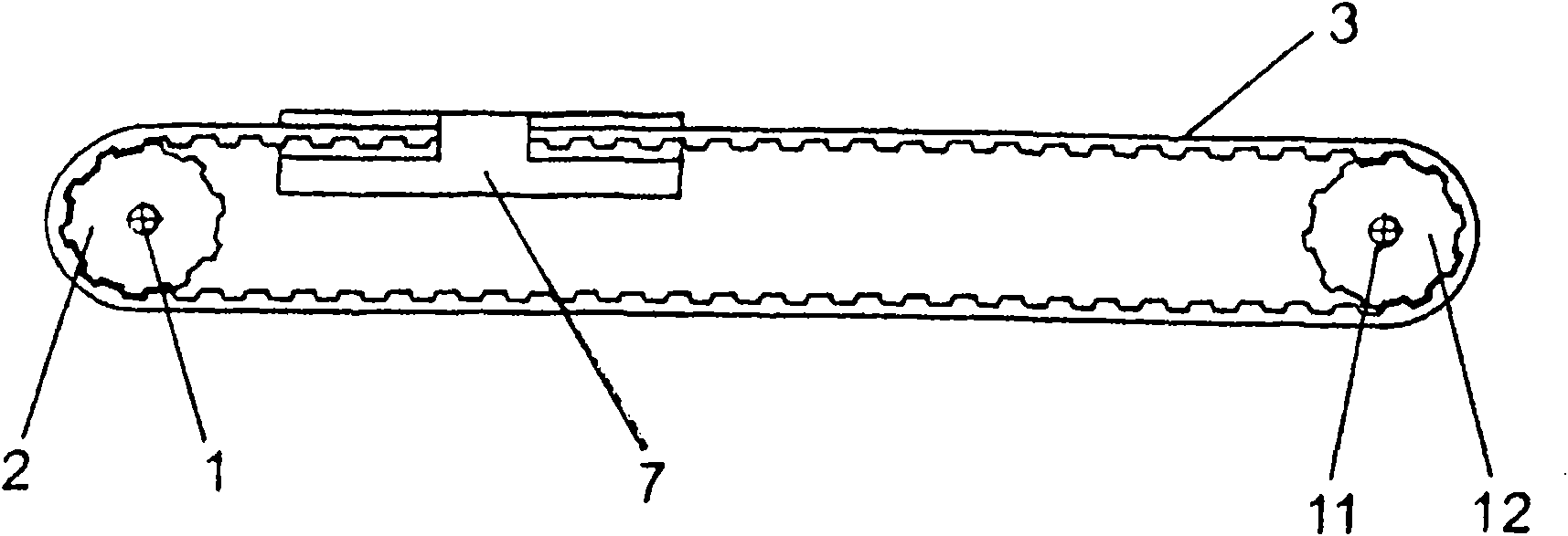
[0028] figure 1 2 shows an arrangement corresponding to the prior art O, wherein the linear shaft 7 moves between the roller 2 of the driving shaft 1 and the roller 12 of the steering shaft 11 by means of the traction member 4 .

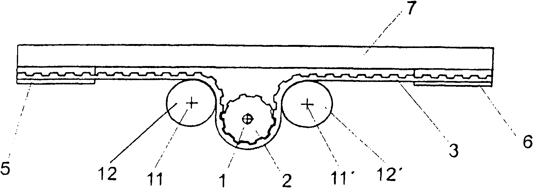
[0029] Figure 2a shows an arrangement of Ω corresponding to the prior art, wherein the linear axis 7 is moved by means of the traction element 4 . Here, the traction element 4 is driven by the roller 2 of the drive shaft 1 and guides the linear shaft 7 by means of reverse rotation through the rollers 12 , 12 ′ of the steering shaft 11 , 11 ′.

[0030] Figure 2b shows the Ω arrangement corresponding to the prior art, wherein the linear axis 7 ("trolley") moves by means of the traction element 4, the roller 2 of the drive shaft 1 and the two rollers 12, 12, 12' lies on said linear axis.

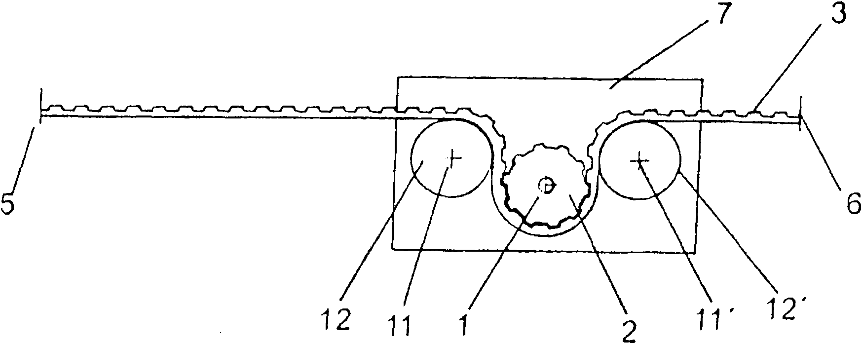
[0031] image 3 shows a device according to the invention for converting a rotary motion into a linear motion, wherein an end-limited traction element 4 (tooth...


PUM


Abstract

The invention relates to an apparatus for converting rotary motion into linear motion, specifically to a belt transmission device, which has at least one drive shaft 1 driven by a driving device 8 and at least one steering shaft 11, wherein the drive shaft and the steering shaft can be provided with rollers (2, 12), the rollers (2, 12) can guide a traction piece 4, the rotational axis 13 of the steering shaft 11 can be sloped relative to the rotational axis 3 of the drive shaft 1 or be sloped in such a degree by aid of one adjusting device 10, so that the traction piece 4 guided by the rollers (2, 12) can move through sideward without contact at the roller 2 part of the drive shaft 1 and at the roller 12 part of the steering shaft 11, the steering of the traction piece 4 is performed on the driving device 8.

Description

technical field [0001] The invention relates to a device for converting a rotary motion into a linear motion, in particular a belt drive, which has at least one drive shaft which can be driven by a drive and at least one steering shaft, which can be arranged There are rollers, wherein a traction element can be guided via the rollers, wherein the axis of rotation of the steering shaft is so inclined or tiltable by means of an adjustment device that the axis of rotation of the steering shaft is inclined to such an extent that The traction element can pass by without contact at the rollers of the driving shaft and the rollers of the steering shaft. Background technique [0002] Currently known are mainly two methods for converting a rotary motion into a linear motion using traction elements (cf. figure 1 and Figure 2). They differ mainly in the arrangement of the traction elements, the number of alternating bends of the traction elements, the minimum number of steering shafts...

Claims


Application Information

Patent Timeline
Patent Type & Authority Patents(China)
IPC IPC(8): F16H19/02B29C45/17
CPCF16H2019/0668F16H19/06B23Q5/38B23Q5/34F16H19/0672B25J9/10F16H19/02F16H2019/0613
Inventor P·W·蔡泽G·M·胡贝尔
Owner ENGEL AUSTRIA
Why Eureka
Try Eureka