Apparatus for cutting, centering or retaining a cable in a stripping head, and cable-stripping device

a technology for stripping heads and cables, applied in the direction of electrical cable installations, apparatus for removing/armouring cables, electrical equipment, etc., can solve the problems of reducing the permissible drive torque, unfavorable cutting, and unfavorable cutting

Pending Publication Date: 2022-02-17
SCHLEUNIGER
View PDF0 Cites 0 Cited by
  • Summary
  • Abstract
  • Description
  • Claims
  • Application Information

AI Technical Summary

Benefits of technology

[0031]In another preferred embodiment of the present invention, the tools are centering jaws. A cable can thereby be precisely centered and / or held.
[0032]In another preferred embodiment of the present invention, the shape of the sheathing of a cable is able to be changed using the tools. The sheathing of a cable can thereby be pressed around with tools that are standing still, or widened through kneading, or the sheathing can be reshaped by means of tools rubbing on it or rotating tools rolling off of it.

Problems solved by technology

A knife or centering jaws adjustment through a differentiated drive with the aid of two synchronously driven motors is costly in terms of control technology and involved, whereby, depending upon the load torque and rotational speed, a small lag error always sets in, which results in an undesired displacement of the knife and / or centering jaws opening.
These have however the drawback that with increasing rotational speed the permissible drive torque decreases, so that the rotational speed during cutting must be limited in order to keep the risk of lag errors and step losses within limits.
During blade drive, step losses would bring about discrete errors of cutting depth until the next referencing.
Likewise, during centering jaws drive, step losses would bring about discrete errors in the guide diameter.

Method used


Image

  • Apparatus for cutting, centering or retaining a cable in a stripping head, and cable-stripping device
  • Apparatus for cutting, centering or retaining a cable in a stripping head, and cable-stripping device
  • Apparatus for cutting, centering or retaining a cable in a stripping head, and cable-stripping device

Examples


Embodiment Construction

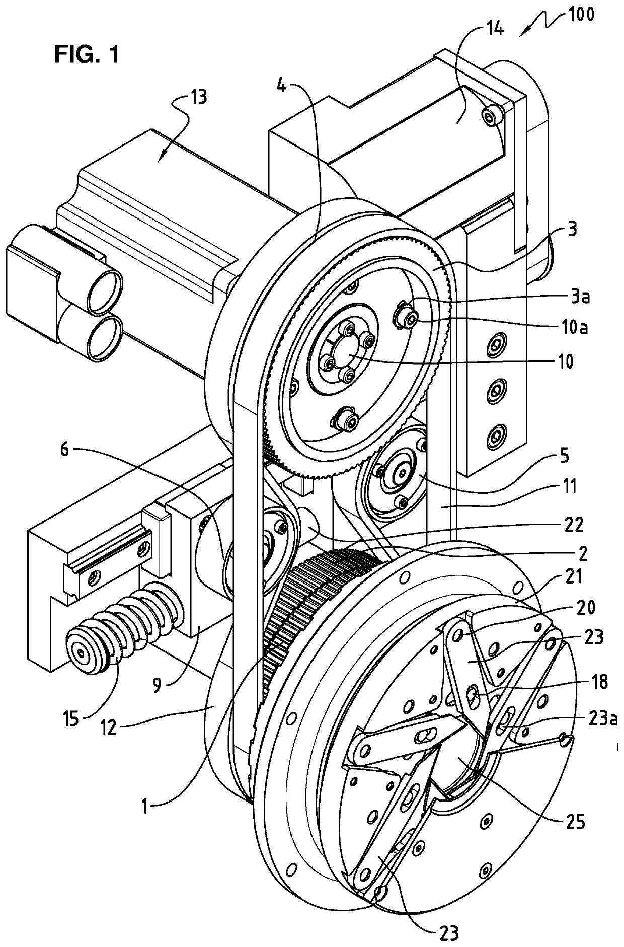
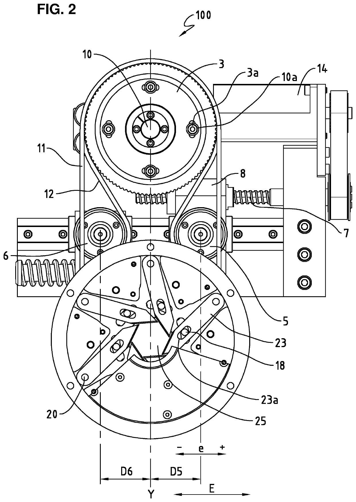
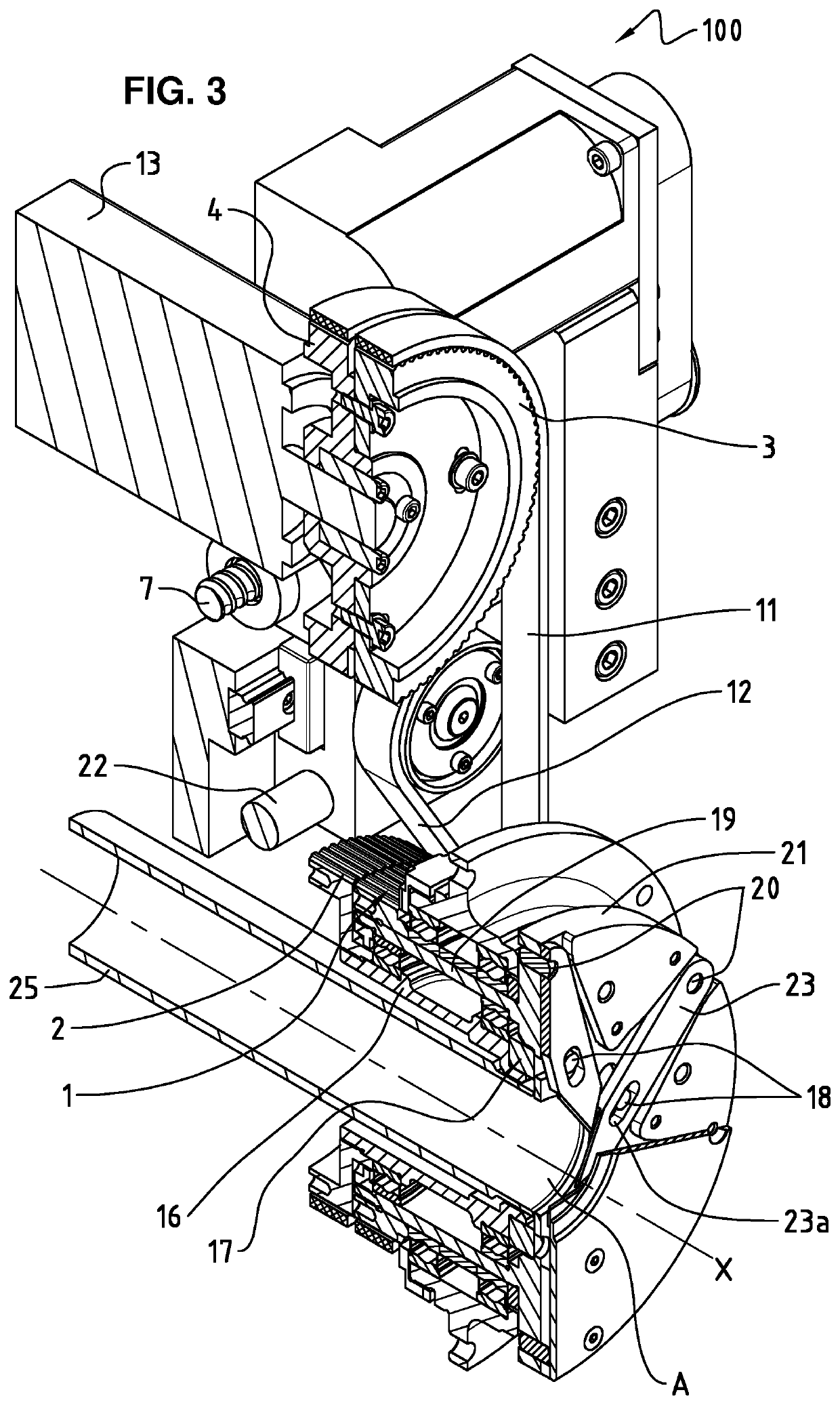
[0044]FIG. 1 shows a perspective view and FIG. 2 a front view of a first embodiment of an apparatus 100 according to the invention. In this embodiment, a third toothed belt wheel 3 and a fourth toothed belt wheel 4 are driven with the same drive shaft 10 by a common drive means, here by a first motor 13. Toothed belt wheels 3 and 4 are screwed by means of screws 10a and therefore turn synchronously. Toothed belt wheel 3 has slotted holes 3a, which can be used for a relative angular rotation of the toothed belt wheels 3 and 4 to adjust the knife opening.

[0045]The third toothed belt wheel 3 drives via a first toothed belt 11 a first toothed belt wheel 1, and the fourth toothed belt wheel 4 drives via a second toothed belt 12 a second toothed belt wheel 2. The first toothed belt wheel 1 and the second toothed belt wheel 2 thus turn coaxially and synchronously. The first toothed belt wheel 1 and the second toothed belt wheel 2 are however rotatably mounted in an angularly adjustable way...


PUM


Abstract

The present invention relates to an apparatus (100, 200, 300) for cutting, centering or holding a cable in a stripping head, comprising a first toothed belt wheel (1) and a second toothed belt wheel (2), which are rotatable coaxially and synchronously, but however in an angularly adjustable way with respect to one another, about a rotational axis (X), as well as a tool flange (21) coaxially connected to the first toothed belt wheel (1), in which a central opening (A) is disposed, through which the cable is able to be led or passed, the tool flange 21 comprising one or more movably attached tools (23), whereby the tools (23) are movable in relation to the rotational axis (X) by means of the positioning means (18) connected to the second toothed belt wheel (2), characterized in that the radial distance of the tools (23) to the rotational axis (X) is adjustable through an angular rotation between the first toothed belt wheel (1) and the second toothed belt wheel (2), which are driven by a common drive means (13). Moreover the present invention also relates to a cable-stripping device comprising an apparatus according to the invention.

Description

TECHNICAL FIELD[0001]The present invention relates to an apparatus for stripping heads, in particular to an apparatus for cutting, centering or holding a cable in a stripping head. The invention especially relates to an apparatus for a rotary cutting stripping head, which is required primarily for stripping of coaxial cables, but also for other cables and wires. Blades thereby rotate around the cable and are advanced radially to the desired cutting depth. Moreover the present invention also relates to an apparatus with which a cable can be centered or held in a stripping head by means of centering jaws. Furthermore the present invention also relates to a cable-stripping device which comprises an apparatus according to the invention.STATE OF THE ART[0002]With a coaxial cable, the stripping is carried out in stages. Usually the first cut severs the outer protective sheath and the screen or shield, whereupon the severed layers are immediately removed. Afterwards the dielectric is incis...

Claims


Application Information

Patent Timeline
Patent Type & Authority Applications(United States)
IPC IPC(8): H02G1/12
CPCH02G1/1265
Inventor BLICKENSTORFER, WILLIDESCHLER, RAPHAEL
Owner SCHLEUNIGER
Why Eureka
Try Eureka