
Apparatus for electrically connecting at least one electrical component to a first and second busbar

a technology for electrical components and busbars, which is applied in the direction of laminated busbars, open busbar installations, power conversion systems, etc., can solve the problems of electrical losses on the busbars, short circuits, and tight limits on a generous spatial arrangement of busbars and electrical components, so as to improve the protection against flashover

Active Publication Date: 2019-11-26
SIEMENS AG
View PDF12 Cites 0 Cited by
  • Summary
  • Abstract
  • Description
  • Claims
  • Application Information

AI Technical Summary

Benefits of technology

This patent is about an apparatus that connects electrical components to busbars. It is designed to be space-saving and to improve protection against flashovers. The invention takes into account air gaps and leakage paths during the design of the electrical connections to prevent flashovers and their destructive effect. The technical effect of this patent is to provide a safer and more efficient connection between electrical components and busbars.

Problems solved by technology

For reasons of environmental conditions, however, tight limits are usually imposed on a generous spatial arrangement of the busbars and the electrical components.
The smaller the separation between busbars with different potentials in operation is selected to be, the greater is the danger that, due to insufficiently dimensioned air gaps or leakage paths between the two busbars, a short-circuit occurs in the form of a flashover.
Electrical losses on the busbars which can have negative effects, in particular, on the efficiency, the availability and / or the operating life of the busbars and of the electrical components connected to the busbars are intrinsic to the system under these conditions and can only be kept within acceptable economic and technical limits with generous or over-dimensioned design of the busbars, the electrical connections and possibly also the electrical components attached to the busbars.

Method used


Image

  • Apparatus for electrically connecting at least one electrical component to a first and second busbar
  • Apparatus for electrically connecting at least one electrical component to a first and second busbar
  • Apparatus for electrically connecting at least one electrical component to a first and second busbar

Examples


Embodiment Construction

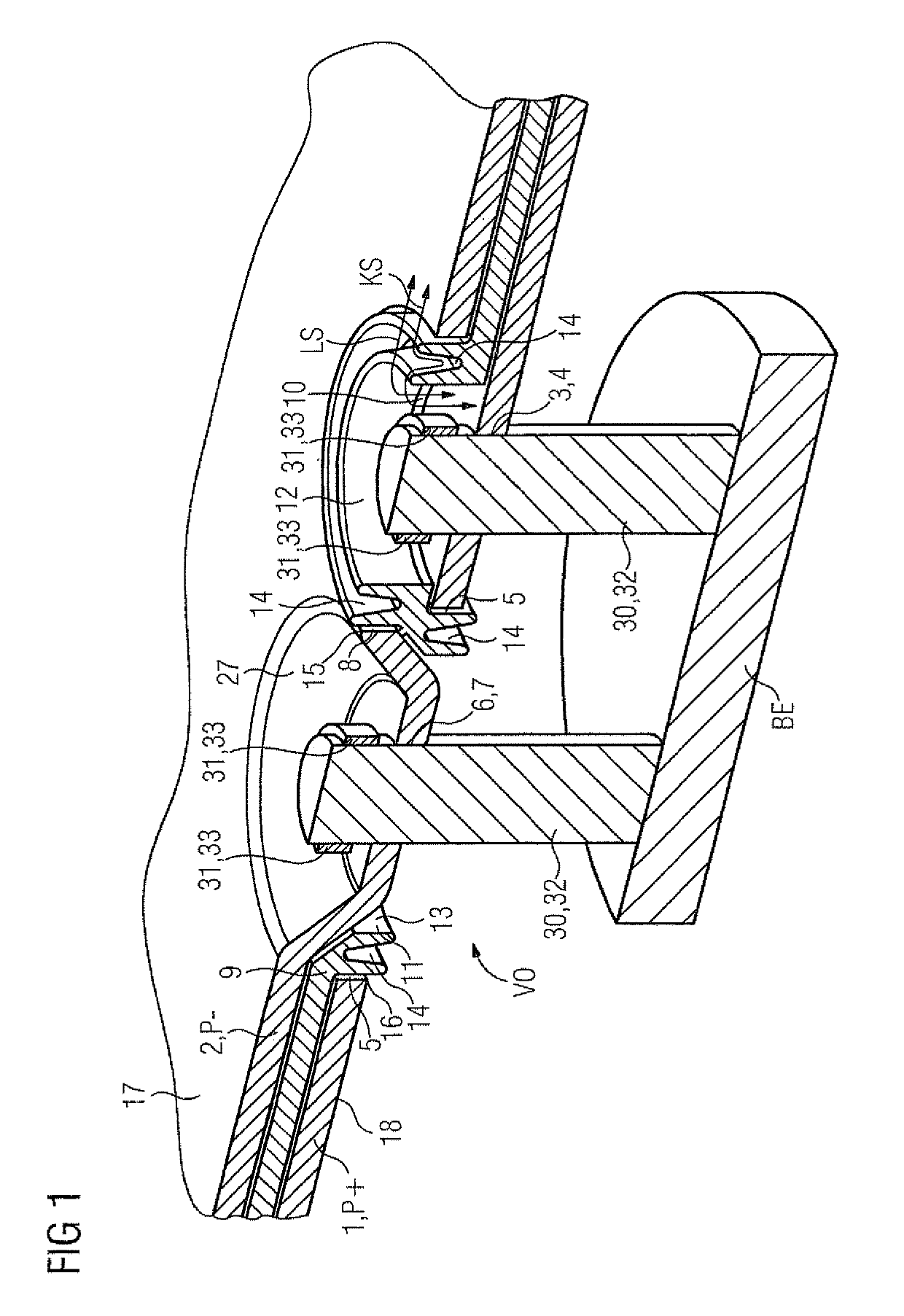
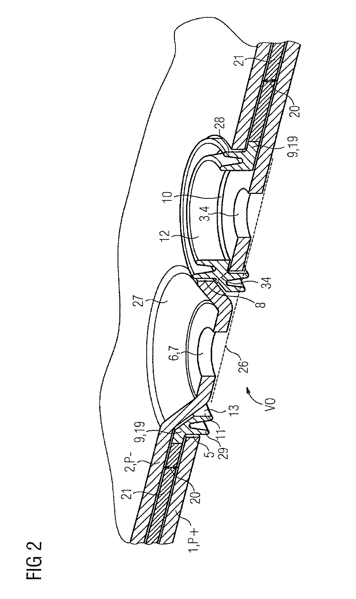
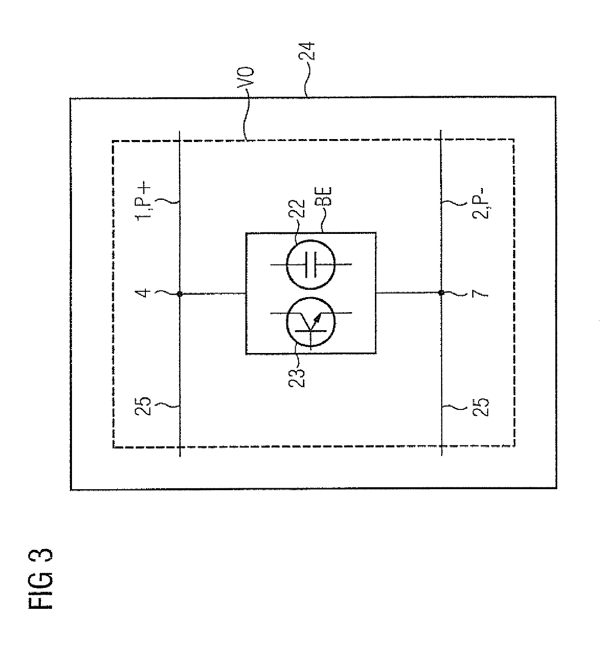
[0048]FIG. 1 shows the apparatus VO according to the invention for electrically connecting at least one electrical component BE to a first and second busbar 1, 2. During electrical operation, the two busbars 1, 2 have a different potential P+, P− to one another. Arranged between the first and second busbar 1, 2 is an insulation means 9 which has a first and a second insulation means opening 10, 11. This insulation means 9 has the task of insulating the two busbars 1, 2 from one another electrically.

[0049]Arranged on the first busbar 1 is a first busbar opening 3, provided as a first electrical connection 4, and a second busbar opening 5. Arranged on the second busbar 2 is a third busbar opening 6, provided as a second electrical connection 7, and a fourth busbar opening 8. The first insulation means opening 10, the first busbar opening 3 and the fourth busbar opening 8 overlap just like the second insulation means opening 11, the third busbar openings 6 and the second busbar opening...


PUM


Abstract

Apparatus for electrically connecting an electrical component to first and second busbars of different potential to one another during operation includes an insulation arranged between the first and second busbars and having first and second openings. The first busbar has a first busbar opening, intended as a first electrical connection, and a second busbar opening. The second busbar has a third busbar opening, intended as a second electrical connection, and a fourth busbar opening. The first opening of the insulation, the first busbar opening and the fourth busbar opening overlap, and the second opening of the insulation, the third busbar openings and the second busbar openings overlap. The insulation has a first boundary which demarcates the first insulation opening and projects into the fourth busbar opening of the second busbar, and a second boundary which demarcates the second opening and projects into the second busbar opening of the first busbar.

Description

CROSS-REFERENCES TO RELATED APPLICATIONS[0001]This application is the U.S. National Stage of International Application No. PCT / EP2017 / 065828, filed Jun. 27, 2017, which designated the United States and has been published as International Publication No. WO 2018 / 007202 and which claims the priority of European Patent Application, Serial No. 16178299.0, filed Jul. 7, 2016, pursuant to 35 U.S.C. 119(a)-(d).BACKGROUND OF THE INVENTION[0002]The invention relates to an apparatus for electrically connecting at least one electrical component to a first and second busbar, which busbars have a different potential to one another during electrical operation. The invention further relates to a converter which comprises the apparatus.[0003]In converters of relatively high output, for electrical energy transmission in a DC network, in general, busbars with a large cross-section and a large surface area are used which enable an electrical connection from electrical or electronic components to the D...

Claims


Application Information

Patent Timeline
IPC IPC(8): H02G5/00H02G5/02H01B17/58H02M7/00
CPCH02G5/02H01B17/58H02M7/003H02G5/005
Inventor NIEBERLEIN, KLAUSOCHS, EWGENIJ
Owner SIEMENS AG
Learn More