Conveying Device for a Fuel Cell Assembly for Conveying and/or Recirculating a Gaseous Medium

a technology of conveying device and fuel cell, which is applied in the direction of batteries/cells, machines/engines, electrochemical generators, etc., can solve the problems of sealing problems and flow losses, and achieve the effect of reducing flow losses and/or pressure reducing flow redirection of gaseous medium, and further reducing flow losses within the conveying devi

Active Publication Date: 2020-11-19
ROBERT BOSCH GMBH
View PDF0 Cites 0 Cited by
  • Summary
  • Abstract
  • Description
  • Claims
  • Application Information

AI Technical Summary

Benefits of technology

[0015]According to an advantageous development, the second flow connection forms a second connection spigot, in particular a cylindrical second connection spigot, having a second internal flow channel, wherein the second connection spigot of the recirculation fan protrudes away from the recirculation fan in the direction of the second flow channel. Furthermore, the second connection spigot of the second flow connection protrudes into a second recess, in particular a cylindrical second recess, of the water separator, wherein a sealing is produced between the second connection spigot and the second recess by a second sealing ring which is located between the outer diameter of the second connection spigot and the inner diameter of the second recess. In this manner, a number of advantages which are described below can be afforded. Consequently, the advantage are afforded that the recirculation fan can be connected in fluid terms to the water separator, wherein the components can be further fixed to each other. In this instance, the second internal flow channel of the recirculation fan can be connected to the outlet of the water separator so that the second flow connection is formed. This has the advantage that the components recirculation fan and jet pump can be connected to each other in fluid terms in a single assembly step in a cost-effective assembly method. This is in contrast to a complex fluid connection using pipework and an additional fixing of the components. The assembly costs of the conveying device can thereby be reduced. Furthermore, the risk of assembly errors in the fluid connection and / or the fixing of the components to each other is reduced, which reduces the probability of failure of the entire conveying device. Furthermore, the advantage can be afforded that a compact and space-saving arrangement of the components recirculation pump and jet pump can be achieved, which in turn reduces the required installation space of the conveying device. A more compact construction of the entire conveying device can thereby be achieved. Furthermore, as a result of the small length of the second flow connection between the water separator and the recirculation pump, a smaller friction loss of the gaseous medium with the inner surface of the second flow connection takes place, whereby the flow loss and / or the pressure loss also remain(s) small. Consequently, the degree of efficiency of the conveying device can be improved. Furthermore, as a result of the construction of the second flow connection as part of the housing of the recirculation fan, a compact and space-saving construction of the conveying device can be achieved. Another advantage can be achieved by the used second sealing ring so that a reliable encapsulation of the second flow connection can be achieved so that a discharge of the gaseous medium can be reduced, whereby the degree of efficiency of the conveying device can be improved.
[0016]According to an advantageous embodiment, the first flow connection is constructed as a first connection plate with the first internal flow channel, wherein the first connection plate is constructed as part of the housing of the recirculation fan, and wherein the first connection plate of the recirculation fan protrudes in the direction of the first flow channel away from the recirculation fan. Furthermore, the housing of the recirculation fan is in abutment by means of the first connection plate with the valve / jet pump arrangement in the direction of the first flow channel, wherein the first sealing ring is located in the direction of the first flow channel and / or peripherally around the first flow channel between the first connection plate and the valve / jet pump arrangement. In this manner, the advantage can be afforded that a positioning of the components recirculation fan and jet pump with respect to each other on the closure plate can be carried out, regardless of tolerance deviations of the components with respect to each other, in particular in the direction of the first flow connection. A rapid assembly can thereby be ensured and the assembly costs can consequently be reduced. Furthermore, the components recirculation fan and jet pump can be connected to each other as a compact assembly group. Furthermore, as a result of the small length of the first flow connection between the components which is possible as a result of the configuration of the first flow connection with the first connection plate, a smaller friction loss of the gaseous medium with the inner surface of the first flow connection takes place, whereby the flow loss and / or the pressure loss remains low. Consequently, the degree of efficiency of the conveying device can be improved.
[0017]According to a particularly advantageous development, the second flow connection is constructed as a second connection plate with the second internal flow channel, wherein the second connection plate of the recirculation fan is constructed as part of the housing of the recirculation fan and wherein the second connection plate of the recirculation fan protrudes in the direction of the second flow channel away from the recirculation fan. Furthermore, the housing of the recirculation fan is in abutment by means of the second connection plate with the water separator in the direction of the second flow channel, wherein the second sealing ring is located in the direction of the second flow channel and / or peripherally around the second flow channel between the second connection plate and the water separator. In this manner, the advantage can be afforded that a positioning of the components recirculation fan and water separator with respect to each other on the closure plate can be carried out regardless of tolerance deviations of the components with respect to each other, in particular in the direction of the first flow connection. A rapid assembly of the components recirculation pump and water separator on each other can thereby be ensured and the assembly costs can consequently be reduced. Furthermore, the components recirculation fan and jet pump can be connected to each other in a compact manner. Furthermore, as a result of the small length of the first flow connection between the components, which is possible as a result of the configuration of the first flow connection with the first connection plate, a smaller friction loss of the gaseous medium with the inner surface of the first flow connection takes place, whereby the flow loss and / or the pressure loss remain(s) low. Consequently, the degree of efficiency of the conveying device can be improved.
[0014]According to a particularly advantageous embodiment of the conveying device, the first flow connection forms a connection spigot, in particular a cylindrical first connection spigot, having a first internal flow channel, wherein the first connection spigot of the recirculation gas protrudes in the direction of the first flow channel away from the recirculation fan. Furthermore, the first connection spigot of the first flow connection protrudes into a first recess, in particular a cylindrical first recess, of the valve / jet pump arrangement, wherein a sealing is carried out between the first connection spigot and the first recess by means of a first sealing ring which is located between the outer diameter of the first connection spigot and the inner diameter of the first recess. In this manner, the advantage can be afforded that the recirculation fan can be connected in fluid terms to the jet pump, and wherein the components can further be fixed to each other. In particular, in this instance, the first internal flow channel of the recirculation fan can be connected to the first inlet of the jet pump so that the first flow connection is formed. This has the advantage that the components recirculation fan and jet pump can be connected to each other in fluid terms in a single assembly step in a cost-effective assembly method and at the same time can be fixed to each other. This is in contrast to a complex fluid connection by means of pipework and / or a distributor plate, on the one hand, and an additional fixing of the components, on the other hand. The assembly costs of the conveying device can thereby be reduced. Furthermore, the risk of assembly errors in the fluid connection and / or the fixing of the components to each other is reduced, which reduces the probability of failure of the conveying device. Furthermore, the advantage can be afforded that a compact and space-saving arrangement of the components recirculation pump and jet pump can be achieved, whereby the required installation space of the conveying device is reduced, which in turn leads to further advantages during transport of the product to the customer and during installation of the conveying device in the fuel cell system and with regard to the spatial requirement in the entire fuel cell system. Another advantage can be achieved by the inserted first sealing ring so that a reliable encapsulation of the first flow connection can be achieved so that a discharge of gaseous medium can be reduced, whereby the degree of efficiency of the conveying device can be improved.

Problems solved by technology

In this instance, there are many flow redirections and consequently flow losses, in particular in all three spatial directions.
Furthermore, the connection of the components of the conveying device by means of pipelines is disadvantageous in that the pipelines over the service-life of the conveying device, in particular in the event of significant temperature fluctuations, can lead to sealing problems, in particular with welded and / or bonded pipelines.

Method used


Image

  • Conveying Device for a Fuel Cell Assembly for Conveying and/or Recirculating a Gaseous Medium
  • Conveying Device for a Fuel Cell Assembly for Conveying and/or Recirculating a Gaseous Medium
  • Conveying Device for a Fuel Cell Assembly for Conveying and/or Recirculating a Gaseous Medium

Examples


first embodiment

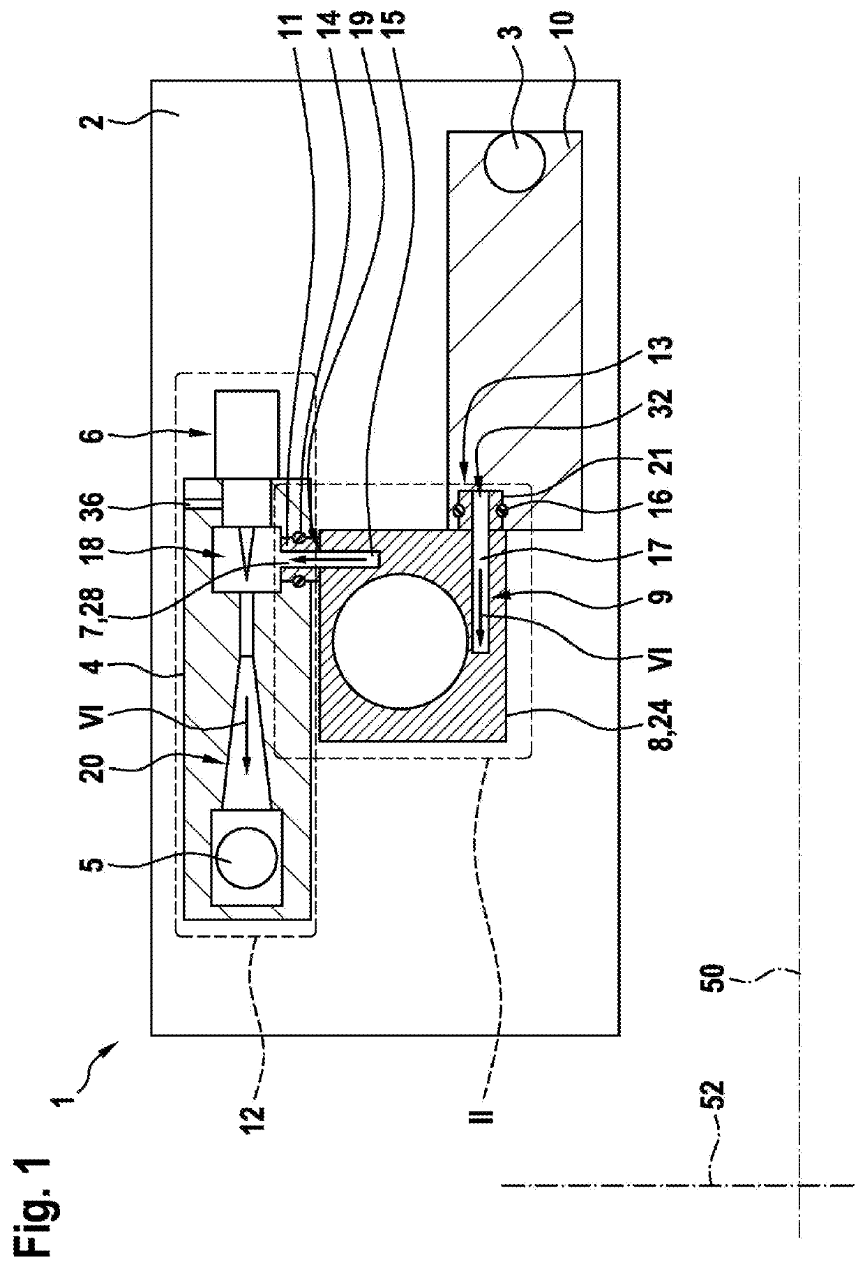
[0025]The illustration according to FIG. 1 is a plan view of a conveying device 1 according to the invention.

[0026]FIG. 1 shows that the conveying device 1 has a plate-like carrier element 2, on which the components jet pump 4, metering valve 6, recirculation fan 8 and water separator 10 are fitted. The conveying device 1 serves in this instance to convey and / or recirculate a gaseous medium, in particular H2. Furthermore, the jet pump 4 is driven by a pressurized gaseous medium, wherein the pressurized gaseous medium, which is in particular a propellant, is supplied to the jet pump 4 by means of the metering valve 6. In addition, the metering valve 6 and the jet pump 4 form a combined valve / jet pump arrangement 12, wherein the metering valve 6 is integrated at least partially in the jet pump 4. The combined valve / jet pump arrangement 12 additionally has a first inlet 28, a second inlet 36, an intake region 18 and a diffuser region 20. The recirculation fan 8 forms a first flow conne...

second embodiment

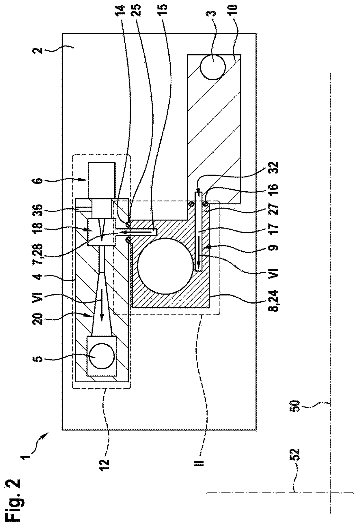
[0031]FIG. 2 is a plan view of the conveying device 1 according to the invention. In this instance, the first flow connection 7 is constructed as a first connection plate 25 to the first internal flow channel 15, wherein the first connection plate 25 is constructed as part of the housing 24 of the recirculation fan 8 and wherein the first connection plate 25 protrudes in the direction of the first flow channel 15 away from the recirculation fan 8. Furthermore, the housing 24 of the recirculation fan 8 is in abutment with the valve / jet pump arrangement 12 in the direction of the first flow channel 15 by means of the first connection plate 25, wherein the first sealing ring 14 is located in the direction of the first flow channel 15 and / or peripherally around the first flow channel 15 between the first connection plate 25 and the valve / jet pump arrangement 12.

[0032]It is further shown in FIG. 2 that the second flow connection 9 is constructed as a second connection plate 27 with the s...


PUM

PropertyMeasurementUnit
pressureaaaaaaaaaa
outer diameteraaaaaaaaaa
inner diameteraaaaaaaaaa

Abstract

A conveying device for a fuel cell system for conveying and / or recirculating a gaseous medium, in particular hydrogen, includes a recirculation fan, a jet pump that is driven by a motive stream of a gaseous medium that is under pressure, and a metering valve. The gaseous medium is supplied to the jet pump by the metering valve. The conveying device further includes an inlet fluidically connected to an anode outlet of the fuel cell and an outlet fluidically connected to an anode inlet of the fuel cell. The jet pump and the metering valve form a combined valve / jet-pump assembly. The components of the conveying device are positioned on a planar carrier element such that flow lines between and / or within the components extend only parallel to the planar carrier element. The planar carrier element is arranged between the fuel cell and the conveying device.

Description

PRIOR ART[0001]The present invention relates to a conveying device for a fuel cell system for conveying and controlling a gaseous medium, in particular hydrogen, which is provided in particular for use in vehicles having a fuel cell drive.[0002]In the automotive sector, in addition to liquid fuels, gaseous fuels will also become increasingly important in future. In particular in vehicles with a fuel cell drive, hydrogen gas flows have to be controlled. The gas flows are in this instance no longer controlled in a discontinuous manner as with the injection of liquid fuel, but instead gas is removed from at least one high-pressure tank and directed via a supply line of a medium-pressure line system to the conveying device. This conveying device guides the gas via a connection line of a low-pressure line system to a fuel cell.[0003]DE 10 2011 105 710 A1 discloses a conveying device for a fuel cell system for conveying and / or recirculating a gaseous medium, having a recirculation fan and...

Claims


Application Information

Patent Timeline
Patent Type & Authority Applications(United States)
IPC IPC(8): H01M8/04089H01M8/04082B60L50/72F04F5/16
CPCB60K2015/0325B60K2015/03256H01M8/04201B60L50/72B60K2015/03315F04F5/16H01M8/04097F04F5/54
Inventor MAGEL, HANS-CHRISTOPH
Owner ROBERT BOSCH GMBH
Why Eureka
Try Eureka