Improved LED lamp bar

A technology of LED strips and LED bulbs, applied in lighting and heating equipment, semiconductor devices of light-emitting elements, point-like light sources, etc., can solve problems such as short circuits, limited lighting angles, and reduced decorative effects.

Inactive Publication Date: 2012-05-23
深圳晶蓝德灯饰有限公司
View PDF0 Cites 0 Cited by
  • Summary
  • Abstract
  • Description
  • Claims
  • Application Information

AI Technical Summary

Problems solved by technology

[0002] The LED light bar is mainly composed of LEDs, long strip circuit boards and hollow transparent sleeves. The production process is to weld a long string of LED bulbs on the circuit board, and cover a layer of transparent sleeves on the outer layer, which can be made into a constant light mode. All LEDs glow after power on; it can also be equipped with a suitable control circuit to make an LED light bar with a certain on-off function. The common products on the market, such as meteor lights, control the on-off of each LED bulb by a chip. After power on, there is a bright segment of a long string of dense LED bulbs inside that flows down one by one. As we all know, the price of LED bulbs is relatively expensive. Due to the large number of LEDs used in meteor lamps, the cost is high, especially for this type of product. Only when they are together can they play a good decorative effect, which makes the total cost very high. Therefore, most of these products on the market are only made of single-sided lighting, that is, only soldering LED bulbs on one side of the circuit board, thereby relatively reducing its cost.
Because the single-sided light-emitting limits its light-emitting angle, its decorative effect is reduced; some products expand their light-emitting angle by welding LED bulbs on both sides of the circuit board, but this method greatly increases the cost of the product and makes consumption It is difficult for those who use it to accept, and because the hollow transparent plastic tube is used, once the tube is broken, it is easy to cause water to enter the lamp body and cause a short circuit, resulting in quality problems

Method used


Image

  • Improved LED lamp bar
  • Improved LED lamp bar
  • Improved LED lamp bar

Examples


Embodiment Construction

[0013] The present invention will be further described below in conjunction with the accompanying drawings and specific embodiments.

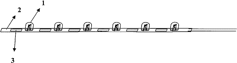
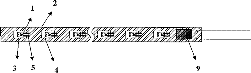
[0014] refer to figure 1 Steady LED light bar, figure 2 LED light strips with control circuits, such as meteor lamps, are used to carry LED light bulbs (1) on the long strip circuit board (2) of the display part, and are regularly spaced next to each LED light bulb (1). Drill holes (3), weld the LED lamp pins (4) to the circuit board (2), and place the LED lamp head (5) in the holes (3). The LED light bulb (1) can emit light on both sides of the circuit board (2) after being powered on, so that the effect of omnidirectional light can be achieved without adding another LED light bulb.

[0015] refer to figure 2 , on the long circuit board (2) used to carry the LED light bulb (1) on the display part of the LED light bar, regularly and periodically punch holes (3) next to each LED light bulb (1), and place the LED light bulb (1) Weld vertica...


PUM


Abstract

The invention relates to an improved LED lamp bar which mainly comprises a display part and a waterproof part, wherein the display part is arranged on a strip circuit board for bearing LED bulbs; holes are regularly punched at intervals beside each LED bulb; LED lamp bases are welded with the circuit board; and LED lamp caps are lay in the holes. The waterproofing method for the waterproof part comprises the following steps: putting the circuit board, which is welded with all the elements, in a waterproof transparent casing, and filling glue in the waterproof transparent casing. The inventionenables an LED lamp bar capable of emitting light on one surface to emit light in all surfaces, and has favorable waterproof property.

Description

technical field [0001] The invention relates to the technical field of decorative lights, in particular to an improved LED light bar. Background technique [0002] The LED light bar is mainly composed of LEDs, long strip circuit boards and hollow transparent sleeves. The production process is to weld a long string of LED bulbs on the circuit board, and cover a layer of transparent sleeves on the outer layer, which can be made into a constant light mode. All LEDs glow after power on; it can also be equipped with a suitable control circuit to make an LED light bar with a certain on-off function. The common products on the market, such as meteor lights, control the on-off of each LED bulb by a chip. After power on, there is a bright segment of a long string of dense LED bulbs inside that flows down one by one. As we all know, the price of LED bulbs is relatively expensive. Due to the large number of LEDs used in meteor lamps, the cost is high, especially for this type of produc...

Claims


Application Information

Patent Timeline
Patent Type & Authority Patents(China)
IPC IPC(8): F21S4/00F21V19/00F21V31/00F21Y101/02F21S4/20F21Y115/10
Inventor 刘世全
Owner 深圳晶蓝德灯饰有限公司
Why Eureka
Try Eureka