Eureka AIR delivers breakthrough ideas for toughest innovation challenges, trusted by R&D personnel around the world.

LED display system

A display system and dynamic display technology, applied in the direction of static indicators, instruments, etc., can solve the problems of complex application support and high production cost, and achieve the effects of convenient application support, low production cost and improved communication speed

Inactive Publication Date: 2010-12-08
HANGZHOU XINXUN TECH CO LTD
View PDF1 Cites 5 Cited by
  • Summary
  • Abstract
  • Description
  • Claims
  • Application Information

AI Technical Summary

Problems solved by technology

[0008] The above-mentioned LED display system, because the data signal passes through all the LED drive circuits on the LED unit boards connected in series, the display refresh rate is limited by the number of LED drive circuits and the communication speed of the LED drive circuits. Most of the LED drive circuits adopt cost control Strict high-voltage, high-current, and large-size technology. Generally, the communication speed does not exceed 30MHZ. When the display resolution is high, in order to ensure the display refresh rate required for the display, the LED control board needs to send multiple sets of communication signals to control multiple sets of strings in sequence. Connected LED unit board, such as figure 2 As shown, in most applications, dozens of sets of control signals are often required, resulting in high production costs and complex application support.

Method used


Image

  • LED display system
  • LED display system
  • LED display system

Examples


Embodiment Construction

[0024] The content of the present invention will be further described below in conjunction with the accompanying drawings.

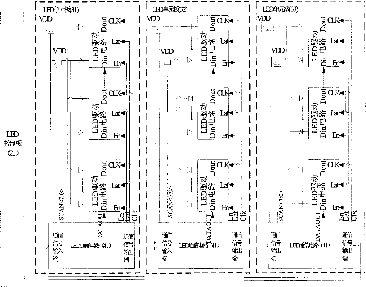
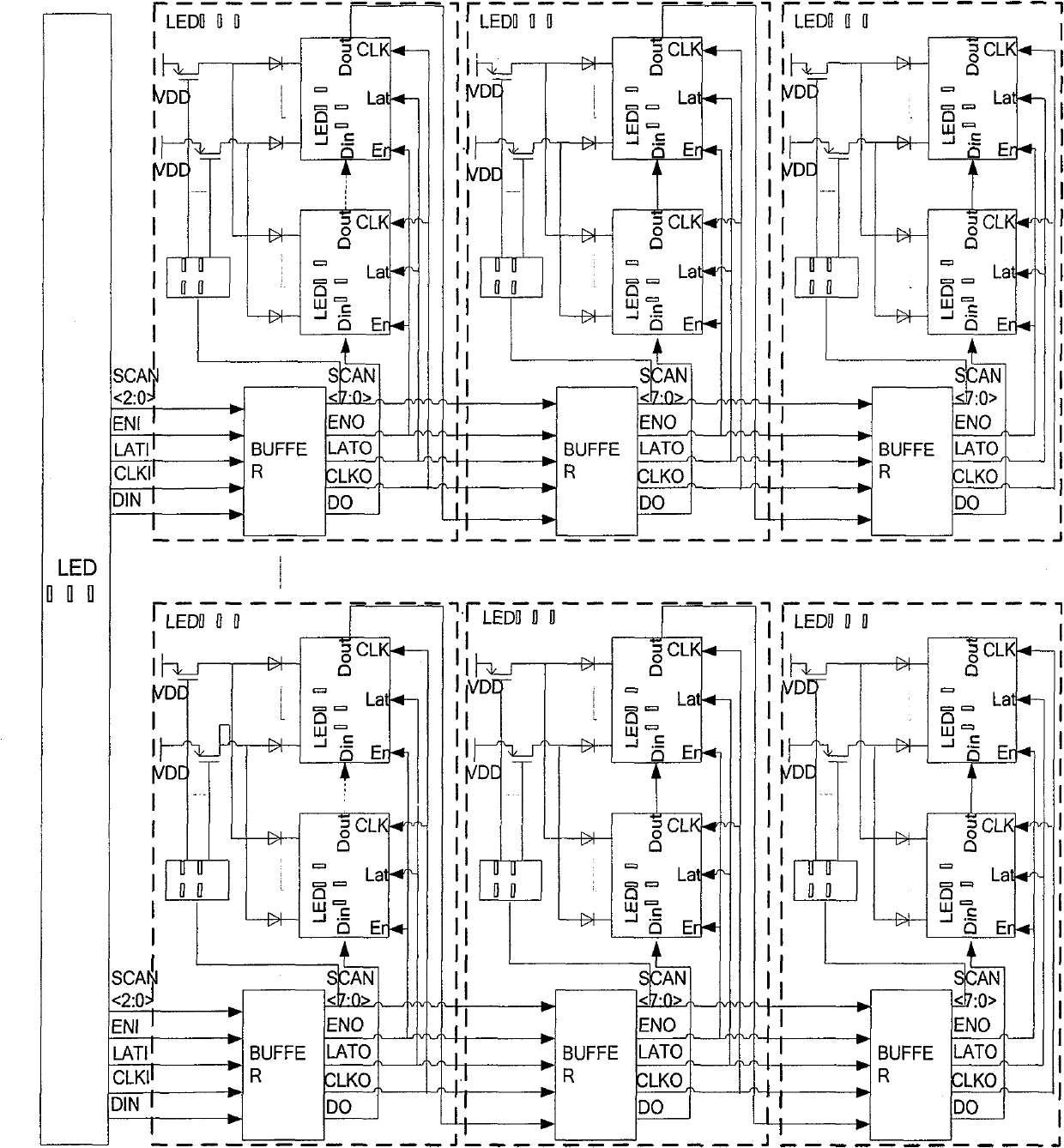
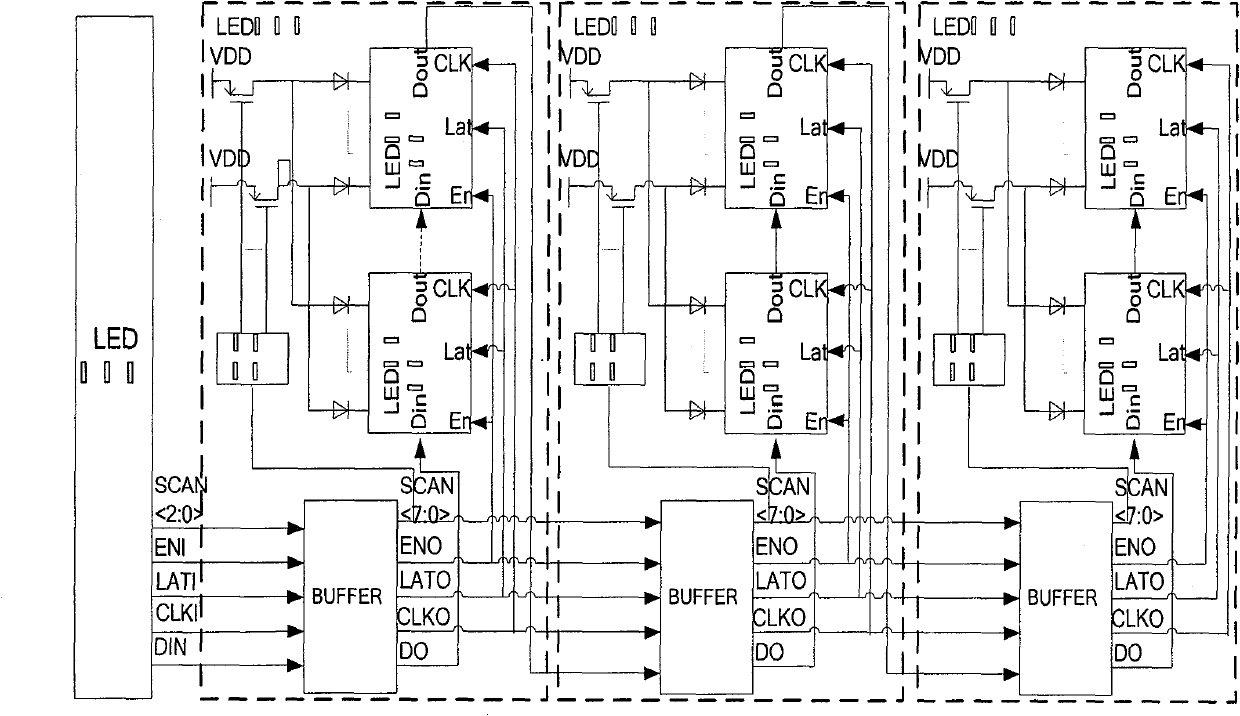
[0025] LED display system, such as image 3 As shown, it includes an LED control board (21) and several LED unit boards (31-3M) connected in series:

[0026] The LED unit board includes an LED communication circuit (41), several switch tubes and several LED drive circuits (51-5N);

[0027] The LED communication circuit (41) includes a communication signal input terminal, a communication signal output terminal, a dynamic display scan timing output terminal (SCAN), a control signal output terminal (En, Lat, Clk), a data output terminal ( DATAOUT);

[0028] The LED control board (21) sends a communication signal to the communication signal input end of the LED communication circuit (41) on the first LED unit board (31), and the communication signal output end of the LED communication circuit of each LED unit board thereafter is connected The communicatio...


PUM


Abstract

The invention discloses an LED display system which comprises an LED control plate and a plurality of LED unit plates connected in series. The LED control plate sends communication signals to a columniation signal input end of an LED communication circuit on the first LED unit plate, the communication signal output end of the LED communication circuit of each LED unit plate is connected with the communication signal input end of the LED communication circuit of next LED unit plate, and the communication signal output end of the LED communication circuit of the last LED unit plate is hung in the air or returns to the LED control plate. The LED communication circuit of each LED unit plate parses out the data according to received communication signal, and provides the data for a first drive circuit data signal input of the LED unit plate through the data output end. A data signal output of each LED drive circuit of the LED unit plate is connected with the data signal input of the next LED drive circuit. The invention has the advantages of high communication speed, low production cost, convenient application support, and the like.

Description

technical field [0001] The invention relates to LED display technology. Background technique [0002] LED display systems widely exist at present, such as figure 1 As shown, it includes an LED control board and several LED unit boards connected in series: [0003] The LED unit board includes a BUFFER circuit that enhances the signal driving capability, a decoding circuit that generates dynamic display scanning timing, several switch tubes and several LED drive circuits; [0004] The communication signals sent by the LED control board include scan signal (SCANI), enable signal (ENI), latch signal (LATI), clock signal (CLKI), data signal (DIN), scan signal sent by the LED control board, enable The signal, latch signal, and clock signal are sequentially driven and enhanced by the BUFFER circuit of each serially connected LED unit board; [0005] The scanning signal (SCANO) enhanced by the BUFFER circuit in each LED unit board is provided to the decoding circuit of the LED un...

Claims


Application Information

Patent Timeline
Patent Type & Authority Applications(China)
IPC IPC(8): G09G3/32
Inventor 赵启永陈帮勇张世侨宋卫权
Owner HANGZHOU XINXUN TECH CO LTD
Why Eureka
Eureka Blog
Learn More