

Color conversion method and corresponding color display method thereof
A color conversion and color technology, applied in static indicators, cathode ray tube indicators, color signal processing circuits, etc., can solve the problems of consuming multipliers and adders, increasing process costs, increasing circuit complexity and the number of components, etc. , to achieve the effect of enriching colors and enhancing the color gamut
- Summary
- Abstract
- Description
- Claims
- Application Information
AI Technical Summary
Problems solved by technology
Method used
Image

Examples
Embodiment Construction
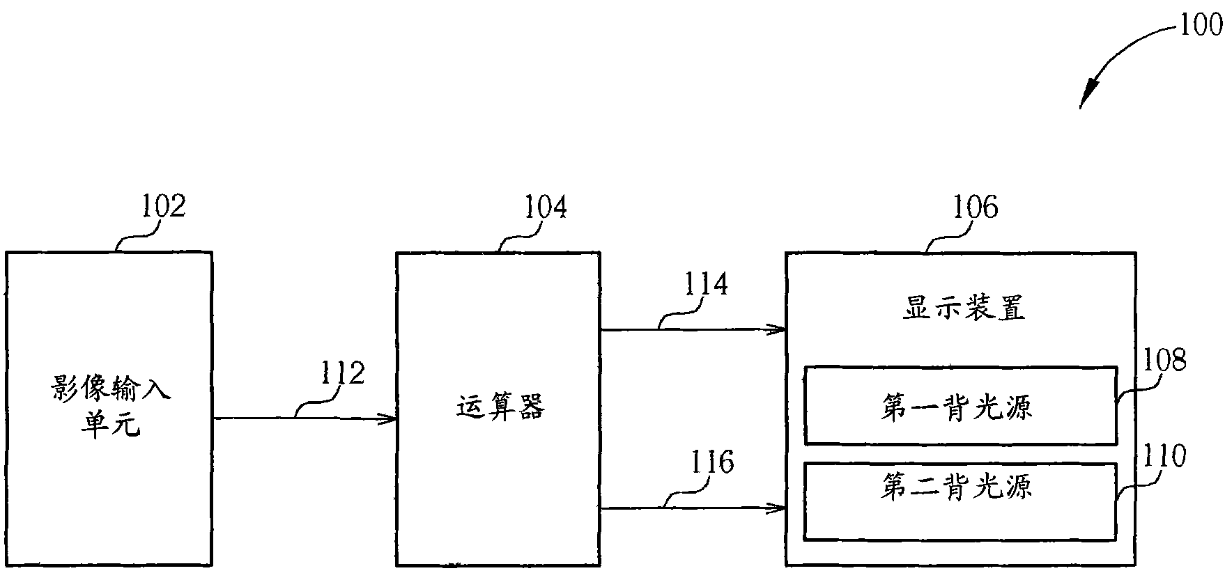
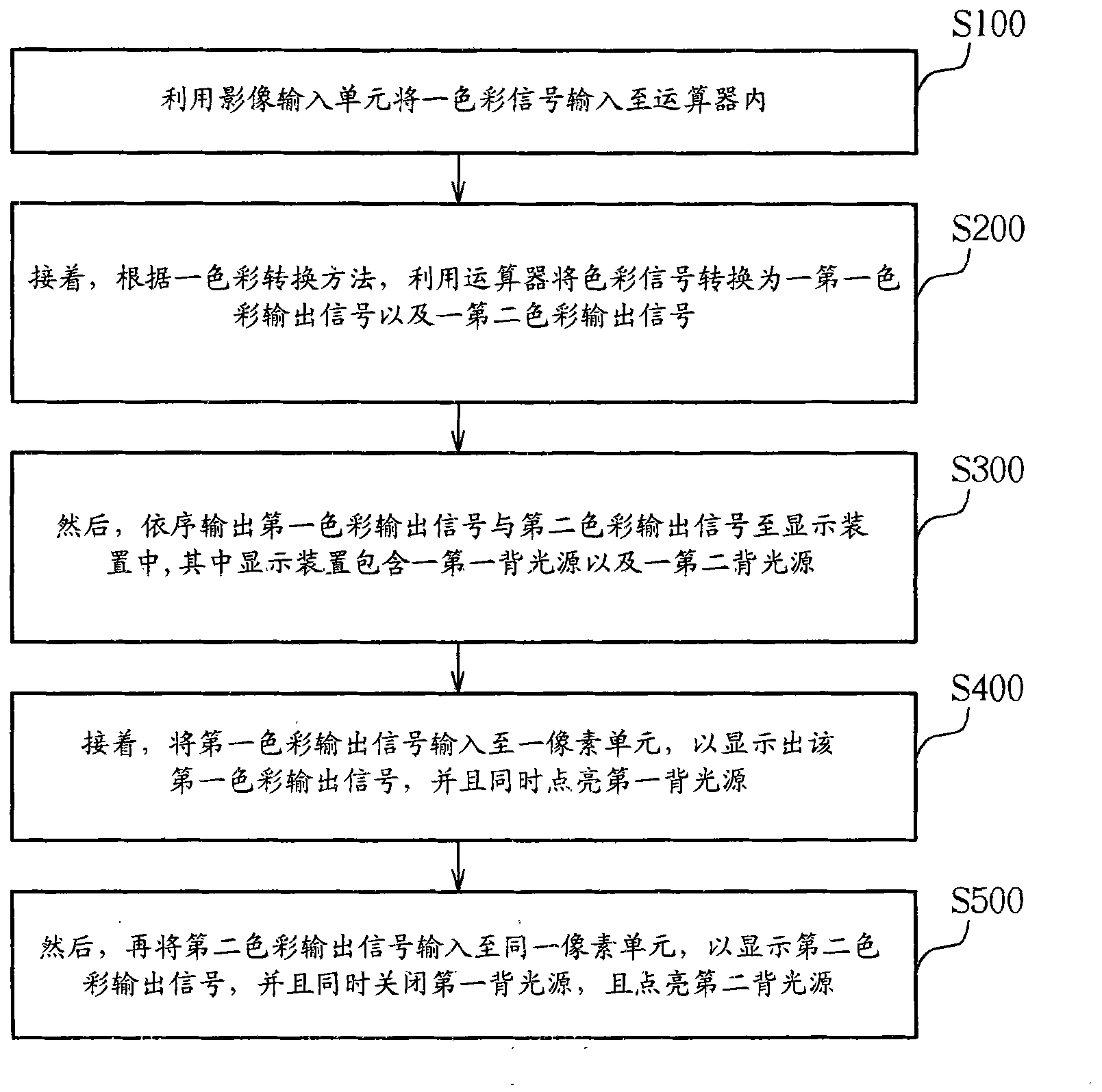
[0024] Please refer to figure 2 and image 3 , figure 2 It is a schematic diagram of a color display system of the present invention, image 3 It is a flowchart of a color display method of the present invention. Such as figure 2 As shown, the color display system 100 of the present invention includes an image input unit 102, an arithmetic unit 104, and a display device 106, wherein the display device 106 includes a plurality of pixel units (not shown), a first backlight source 108 and a second backlight source 110 . Such as image 3 As shown, the color display method of the present invention comprises the following steps:
[0025] Step S100: using the image input unit 102 to input a color signal 112 into the computing unit 104;
[0026] Step S200: Next, according to a color conversion method, use the arithmetic unit 104 to convert the color signal 112 into a first color output signal 114 and a second color output signal 116;
[0027] Step S300: Then, sequentially o...
PUM
 Abstract
Description
Claims
Application Information