Mixing and mincing auger

A technology of screw propellers and mixer trucks, applied in mixers with rotating stirring devices, transportation and packaging, chemical instruments and methods, etc., can solve the problems of increasing cutting and fully chopping time, etc.

Active Publication Date: 2013-08-14
STORTI
View PDF0 Cites 0 Cited by
  • Summary
  • Abstract
  • Description
  • Claims
  • Application Information

AI Technical Summary

Problems solved by technology

This necessarily increases the time required to properly cut and adequately mince the product

Method used


Image

  • Mixing and mincing auger
  • Mixing and mincing auger
  • Mixing and mincing auger

Examples


Embodiment Construction

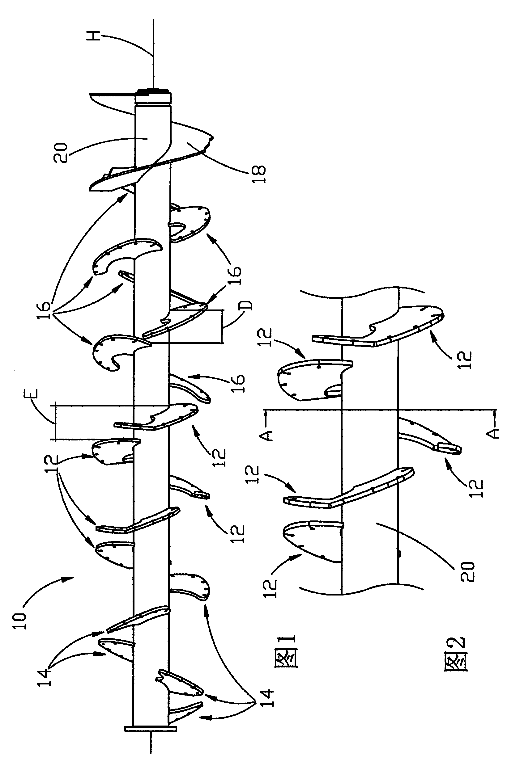
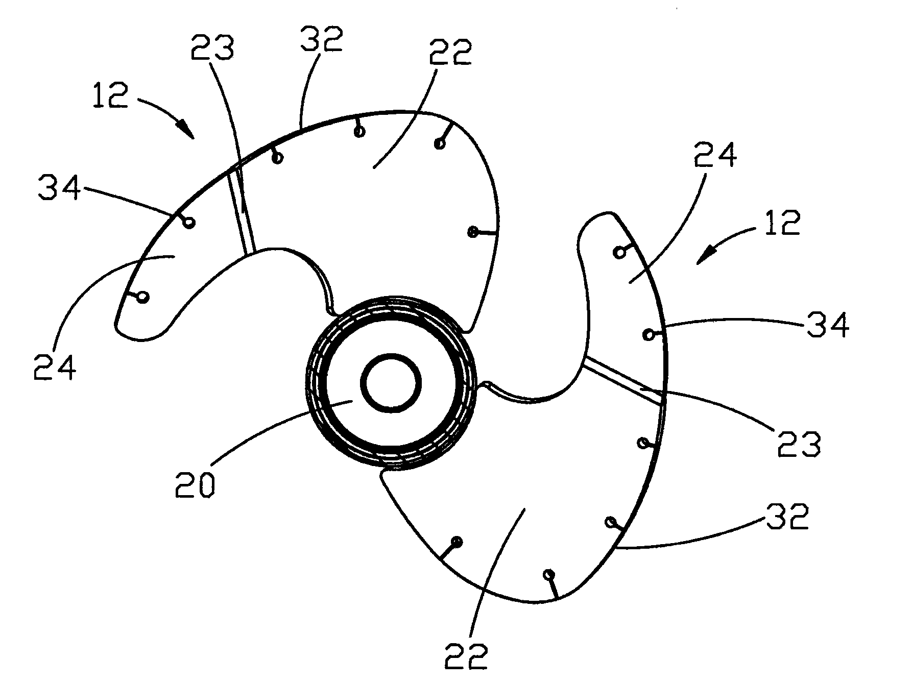
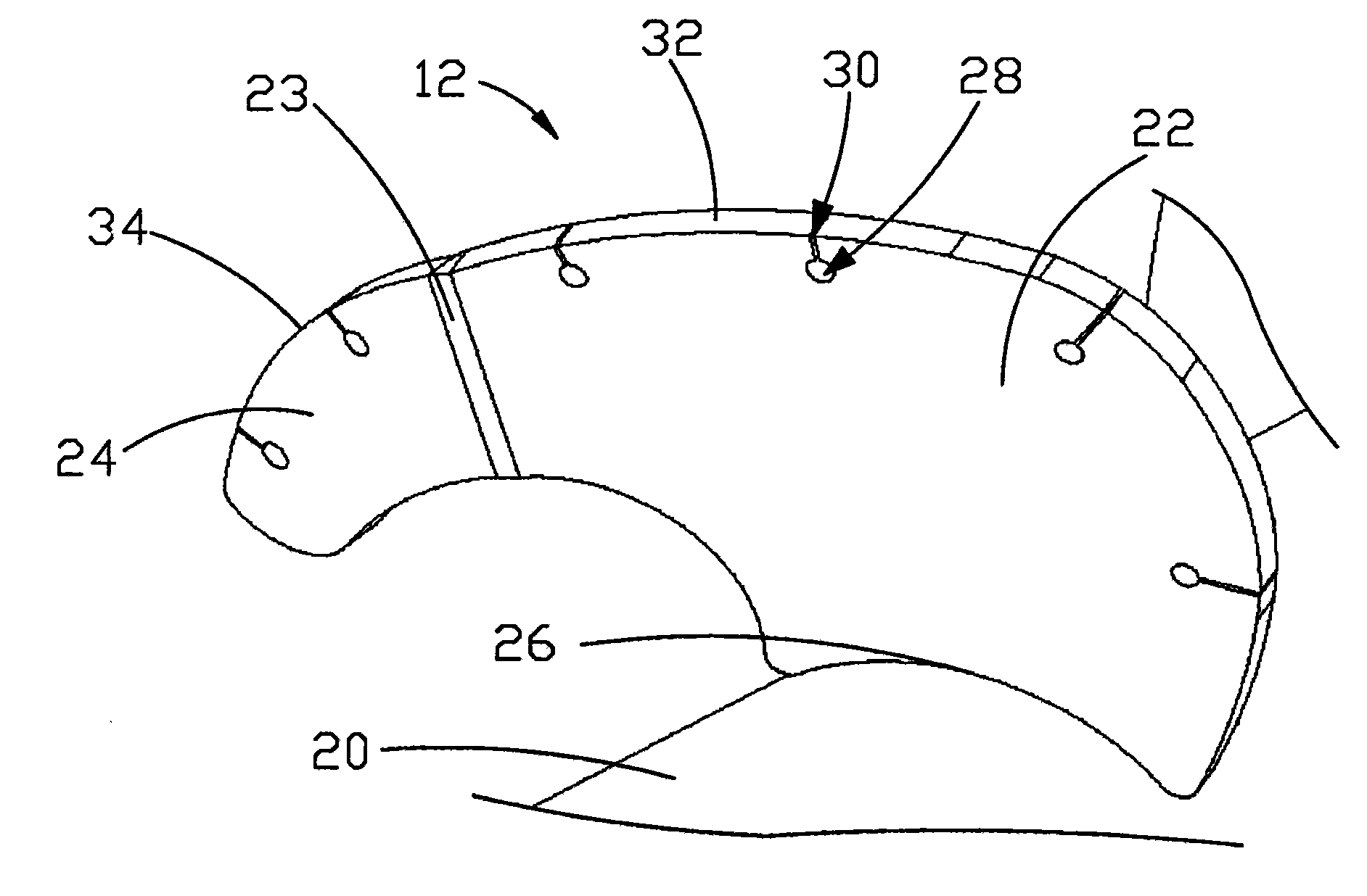
[0026] Looking at the drawings, we use the number 10 to indicate the screw propeller, which includes a rotating shaft 20 that can be mounted eg on the bottom of a mixing and chopping cart. Four different types of blades 12 , 14 , 16 and 18 are wedged on shaft 20 in terms of size and / or shape.

[0027] A helical blade 18 according to a first type of blade is fastened to one end of a shaft 20, and precisely to figure 1 The right end of the axis shown.

[0028] Seven blades 16 shaped according to blades of the second type are fastened to the shaft 20 after the helical blades 18 . The shaft connection portions of these blades 16 lie in a plane inclined with respect to a plane at right angles to the H-axis of the shaft 20 . The blades 16 have a flat shape; more precisely, each lies entirely in a single plane equivalent to the plane of connection to the shaft.

[0029] The successive blades 16 are spaced longitudinally at a constant distance D, and angularly at an angle between 1...


PUM


Abstract

An auger (10), preferably for mincing-mixing wagons, comprising a rotary shaft (20) with H axis and at least one blade (12, 14, 16), including a keying portion (22) on the rotary shaft (20) with, joined to it, a free terminal portion (24). Said keying portion (22) is placed in a plane that is inclined with respect to the plane at right angle to the H axis of said shaft (20), while the free terminal portion (24) of at least one blade (12) is inclined with respect to the keying portion (22).

Description

technical field [0001] The present invention relates to an auger designed to be preferably mounted on a mixing and chopping vehicle. In particular, it describes an auger with blades shaped to achieve increasingly efficient cutting results with less force. Background technique [0002] Shredding carts such as chopping carts for feed are well known. These shredder carts generally consist of self-propelled or towed hoppers with shafts mounted internally on their bottoms. These shafts have one or more augers designed to agitate and chop the feed introduced into the bin. [0003] The shredder trolley usually has a horizontally placed auger which cuts, chops and stirs the feed due to its rotational movement with the aid of for example counter blades placed on the bottom of the hopper. [0004] Known types of screw propellers may have a single helical blade fastened to the rotating shaft, or alternatively they may comprise several blades wedged on the rotating shaft in a positio...

Claims


Application Information

Patent Timeline
Patent Type & Authority Patents(China)
IPC IPC(8): A01K5/00
CPCB01F7/00275B01F13/1044B01F7/00141A01K5/001B01F7/0065A01K5/002B01F2013/108B01F27/0724B01F27/1123B01F27/1921B01F33/8305B01F33/83611
Inventor 恩瑞克·斯托蒂奥托里诺·斯托蒂
Owner STORTI
Why Eureka
Try Eureka