Electrically heatable laminated glazing

A technology of electric heating and heating wires, which is applied in the direction of ohmic resistance heating, electric heating devices, transparent/reflective heating devices, etc., and can solve problems such as injuries

Inactive Publication Date: 2010-12-08
PILKINGTON GROUP LTD
View PDF6 Cites 11 Cited by
  • Summary
  • Abstract
  • Description
  • Claims
  • Application Information

AI Technical Summary

Problems solved by technology

The presence of one or more hot spots in a window is highly undesirable for two reasons: first, there are areas where occupants of a vehicle with the ...

Method used


Image

  • Electrically heatable laminated glazing
  • Electrically heatable laminated glazing
  • Electrically heatable laminated glazing

Examples


Embodiment Construction

[0019] In order to minimize variations in power density along the wire heating window, the invention provides electrical connections (bus bars) that are shaped so that the length of the wires in the array extending between the electrical connections remains substantially constant.

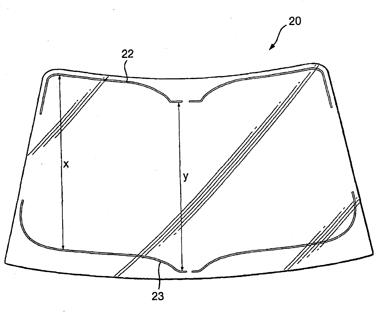
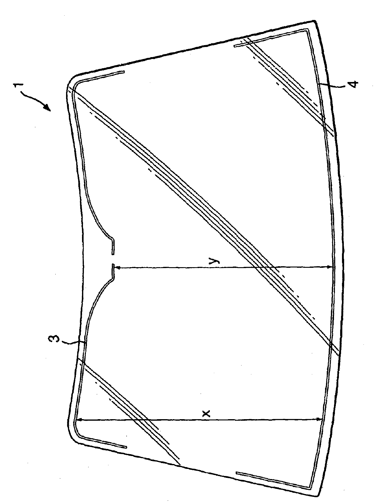
[0020] This concept is best exemplified by first considering a wire heated windshield commonly used in the prior art. figure 1 is a schematic plan view of a wire heated window with wire-free regions according to the prior art. The wire heating window 1 is generally trapezoidal in shape and comprises an array of fine, closely spaced wires 2, only a small portion of which are shown for clarity. The array of wires 2 is bounded by a first electrical connection means or bus bar 3 and a second electrical connection means or bus bar 4 . The wires in the array 2 extend between the first and second electrical connection means 3 , 4 . These electrical connection means 3, 4 connect the array to a power sour...


PUM


Abstract

The invention discloses an electrically heated windowhaving minimised hot spots. The window comprisesat least two plies of a glazing material having a ply of an interlayer material laminated therebetween. An arrayofheating wires is carried by one of the plies, the heating wires extending between a first electrical connection means and a second electrical connection means for supplying current through the wires, the first and second electrical connection means being substantiallyparallelto each other. The first electrical connection means isshaped so as to define a wire-free area to allow a data signal to be transmitted through the window to a device positioned in thevicinity of the wire-free area. The second electrical connection means is shaped to correspond to the first electrical connection means, such that the heating wires in the array have a substantially constant length.

Description

technical field [0001] The present invention relates to electrically heated windows, and more particularly to laminated electrically heated windows (wire heated windows) comprising an array of heating wires. Background technique [0002] Electrically heated windows are commonly used as windshields or mirrors in vehicles to enable defrosting or defogging of the windows during cold and / or wet weather conditions. For windows used as windshields in vehicles, the electric heating device is typically provided as an array of fine (with a diameter of less than 150 μm), closely spaced (wire-to-wire distance between 1 mm and 5 mm) wires. Although the wires in the array are substantially parallel, each wire is provided with an undulation, such as crimping in a sinusoidal, helical, zig-zag, or random pattern, to avoid dazzling and polarization by vehicle drivers when viewing objects through windows Effect. [0003] It is increasingly desirable to be able to send data signals to and fr...

Claims


Application Information

Patent Timeline
IPC IPC(8): B32B17/10H05B3/84H05B3/86
CPCH05B2203/008H05B2203/016H05B2203/002B32B17/10376H05B3/84B32B17/10036B32B17/10761B32B17/10385
Inventor M·A·张伯伦J·B·迪克松
Owner PILKINGTON GROUP LTD
Why Eureka
Try Eureka