Ink pinning assembly

a technology of pinning assembly and pinning plate, which is applied in the direction of printing, other printing apparatus, etc., can solve the problems of significant print aberration, significant print aberration, and sub-standard printed images, and achieve the effect of reducing the ir radiation produced and efficient us

Inactive Publication Date: 2008-05-15
FFEI LTD
View PDF6 Cites 5 Cited by
  • Summary
  • Abstract
  • Description
  • Claims
  • Application Information

AI Technical Summary

Benefits of technology

[0012]We have developed a new and simple radiation guide device which enables a relatively small radiation source to be used, and hence at full power, while at the same time enabling radiation to be emitted from the device in a uniform manner and with uniform intensity. In other words, the assembly creates a uniform illumination from a source that is shorter than the length of the inlet and of the region to be uniformly radiated and has a lower intensity than a full length source would give. In this way, the heat (i.e. IR) radiated onto the substrate is minimised rather than maximised it as in the case of US-A-2005 / 0068396.
[0016]In a typical embodiment, the number of reflections within the radiation guide device is no more than six or seven while some rays can travel directly to the substrate without reflection. Losses due to reflection are thus much smaller than with a conventional light pipe. This enables the more efficient use of the radiation emitted and minimises the IR radiation produced.

Problems solved by technology

Often this spreading is undesirable as it can lead to blurring, running or bleeding within a printed representation.
This produces significant print aberrations and so it is common practice to cure the ink immediately after each print bar has deposited ink onto the printing medium.
Consequentially, this causes errors in the required printing density and generates sub-standard printed images.
During the pin curing, it is also desirable not to dry the printing medium 111 too much as this will cause shrinkage of the printing medium 111, leading to registration errors between the colours.
However, during normal operation, the E / M radiation still needs to be emitted at a significant level to achieve penetration of the printing medium 111 and thus drying of the ink therein.
One problem with running these lamps at less than full power is that this affects the stability of the lamp and also changes the spectral output.
It also further renders the lamp more prone to ambient temperature changes.
Another problem is that electrical control circuitry is required to run the lamps at less than their rated power.
In extreme cases, the printing medium 111 is at risk from catching alight, contributing to a significant health and safety risk.
As these shutters or filters need to cover the whole length of the lamp they generally increase the size of the lamp housing, making it difficult to fit the housing between the print bars and increasing the size of the press.

Method used


Image

  • Ink pinning assembly
  • Ink pinning assembly
  • Ink pinning assembly

Examples


Embodiment Construction

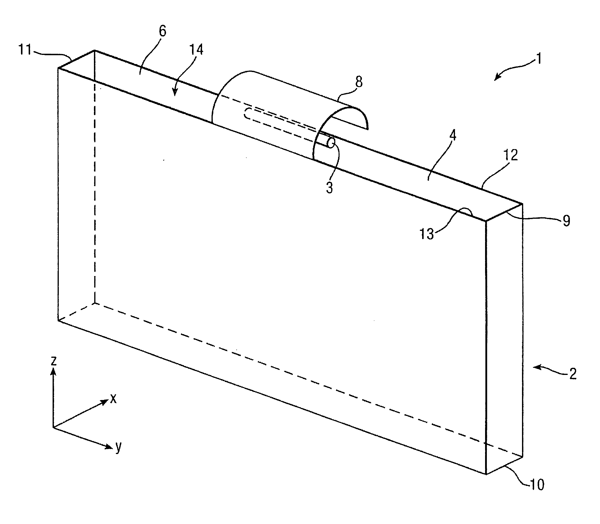
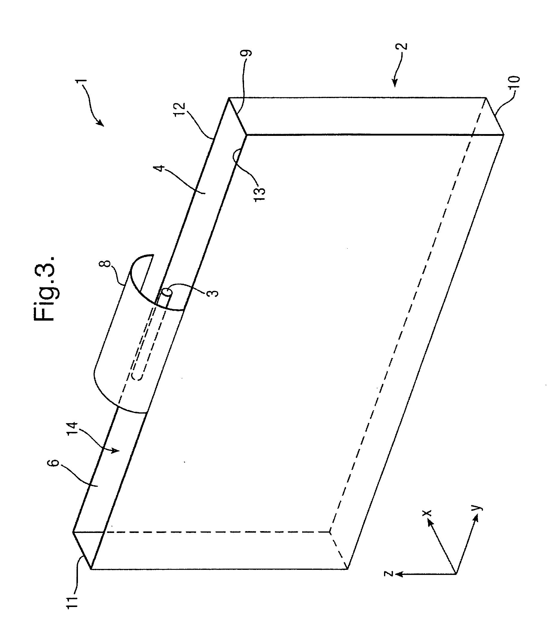
[0028]One arrangement is shown in FIG. 3. Ink curing apparatus 1 comprises an E / M radiation source 3 and an elongate E / M radiation distribution device 2. The E / M radiation source 3 is typically provided by a doped Mercury lamp such as an Iron doped lamp generating UV radiation. The elongate E / M radiation distribution device 2 is in the form of a rectangular box 4 whose sides are defined by four simple, plane reflecting mirrors surrounding a cavity 14. These mirrors include two end surfaces 9, 11, and two side surfaces 12, 13, and an optional lower transparent surface 10 defining an outlet. Alternatively, the outlet could simply be left open. One end 6 of the rectangular box is left open to define an inlet that receives E / M radiation emitted from the E / M radiation source 3. Typical dimensions are 80 mm (length)×10 mm (diameter) for the source and 430 mm (length)×300 mm (height)×40 mm (width) for the box. It will be seen, therefore, that the length of the source 3 is considerably less...


PUM


Abstract

An ink pinning assembly comprises a source of UV radiation suitable for pinning ink on a record medium. A radiation guide device has an inlet facing the source and an outlet through which radiation is emitted towards a record medium, in use, the length of the inlet being greater that the length of the radiation source. The radiation guide device has a substantially rectangular or square wall in plan surrounding a cavity extending between the inlet and outlet, the internal surface of the wall being reflective to the pinning radiation so that pinning radiation with a substantial uniform intensity is emitted from the outlet.

Description

FIELD OF THE INVENTION[0001]This invention relates to ink curing apparatus for use in the curing of inks printed onto a printing medium.DESCRIPTION OF THE PRIOR ART[0002]A modern monotone printing press typically comprises a printing device, such as an industrial inkjet printer and a curing device. Continuous printing presses often further comprise rollers or conveyor belts to transport a printing medium past a series of printing and curing devices. The printing medium is often a substantially continuous sheet that is transported through the press in order to produce a continuous printed output. In this configuration, a printing device typically extends across the width of the printing medium and is referred to as a “print bar”. Once ink has been printed onto the printing medium from a printing device, it first wets, then penetrates, the surface of the printing medium before starting to spread. Often this spreading is undesirable as it can lead to blurring, running or bleeding withi...

Claims


Application Information

Patent Timeline
Patent Type & Authority Applications(United States)
IPC IPC(8): B41J2/01
CPCB41J11/002B41J11/00214B41J11/00218
Inventor GOUCH, MARTIN PHILIP
Owner FFEI LTD
Why Eureka
Try Eureka