
Radar sensor and method for controlling same to reduce the crosstalk of digital signals to the HF radar signal

a technology of radar sensor and crosstalk, which is applied in the field of radar sensor, can solve the problems of unavoidable crosstalk of digital signals into the transceiver device of the radar sensor, affecting the frequency spectrum of the emitted radar signal, and hardly being able to implement the setting of operating parameters

Active Publication Date: 2016-03-15
ROBERT BOSCH GMBH
View PDF24 Cites 0 Cited by
  • Summary
  • Abstract
  • Description
  • Claims
  • Application Information

AI Technical Summary

Benefits of technology

This approach effectively reduces interfering radiation on side lines, ensuring compliance with radiation limiting values while allowing continuous operation for applications like adaptive cruise control without interrupting the radar signal, even with temporarily poor signal quality.

Problems solved by technology

Because of manifold setting possibilities and of operating states to be monitored for safety reasons, it is hardly possible to implement the setting of operating parameters to control the sensor and the readout of operating states in analog form via separate terminals (pins) of the integrated radar sensor component.
Because of the integrated configuration of the radar sensor, however, crosstalk of the digital signals into the transceiver device of the radar sensor is unavoidable.
This results in the occurrence of interfering side lines or side bands in the frequency spectrum of the emitted radar signal during operation of the digital interface.
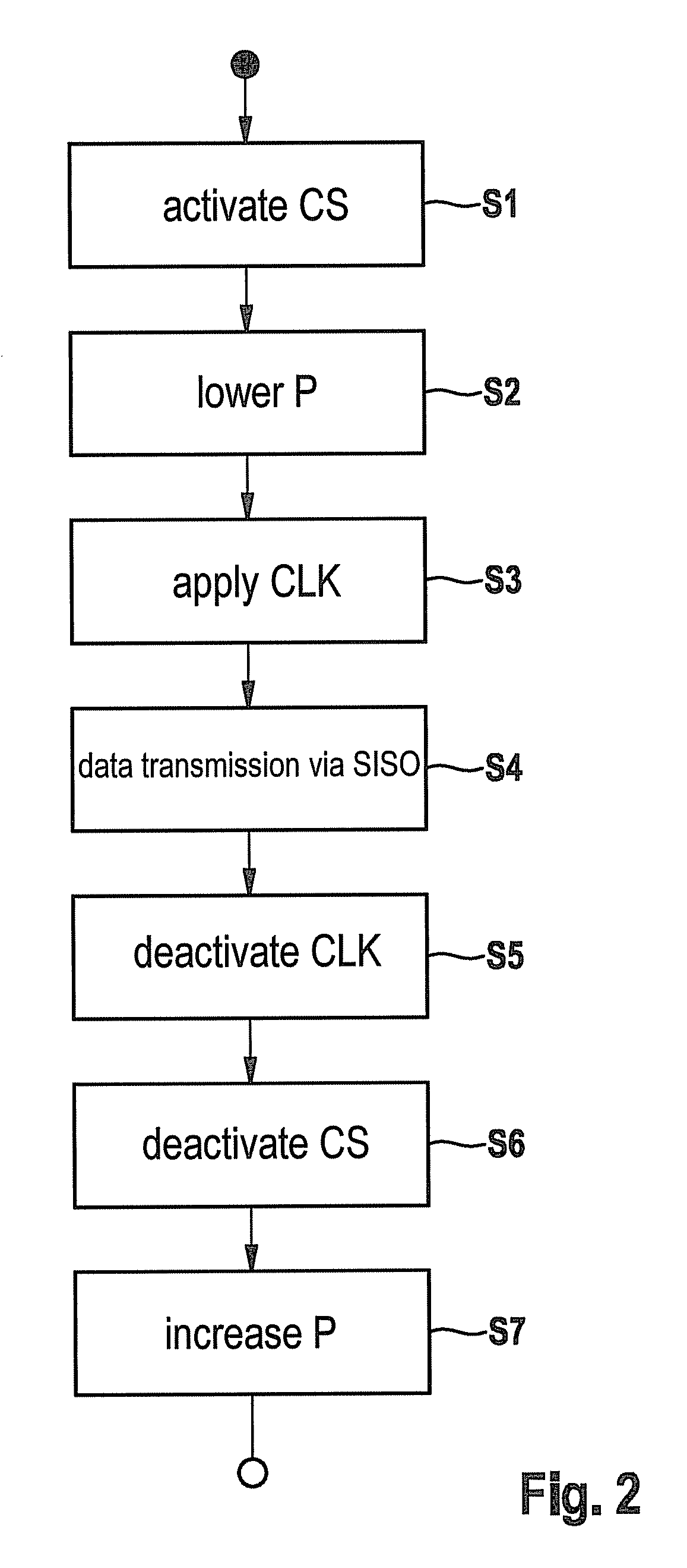
The interfering sideband still occurs, but limiting values may be easily maintained due to the lowered output power.

Method used


Image

  • Radar sensor and method for controlling same to reduce the crosstalk of digital signals to the HF radar signal
  • Radar sensor and method for controlling same to reduce the crosstalk of digital signals to the HF radar signal
  • Radar sensor and method for controlling same to reduce the crosstalk of digital signals to the HF radar signal

Examples


Embodiment Construction

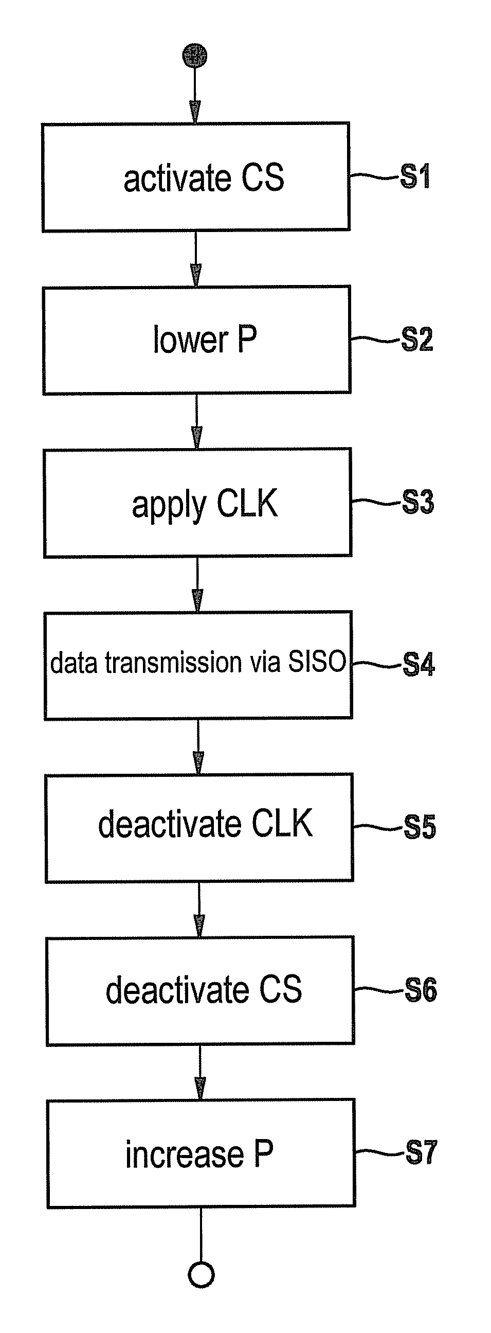
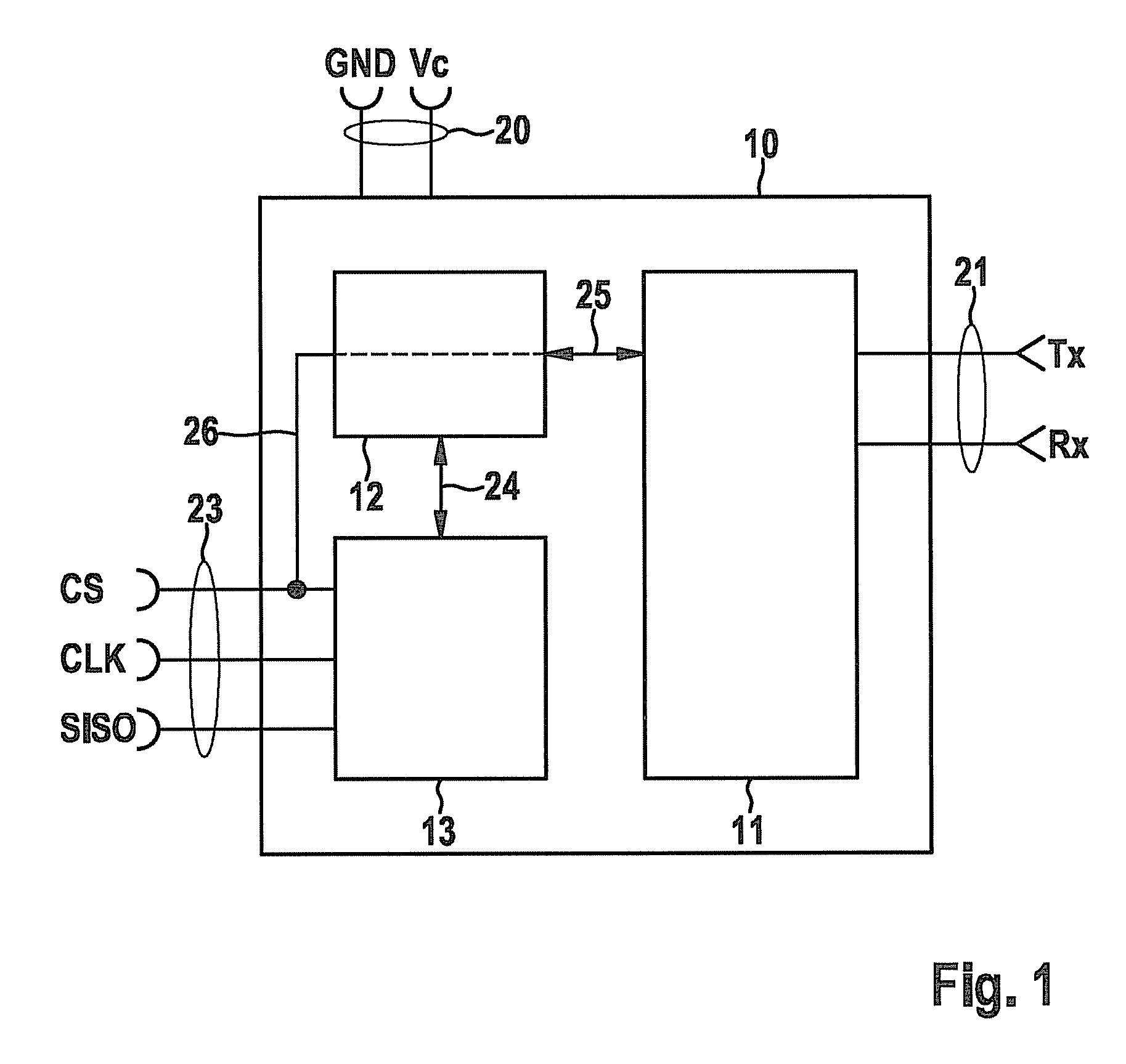
[0012]FIG. 1 shows a radar sensor, implemented as an integrated MMIC component 10, in a block diagram. The radar sensor includes a transceiver device 11 for a high-frequency radar signal, a control unit 12, and an interface unit 13.

[0013]Transceiver device 11 may include a high-frequency oscillator, a reception amplifier, and mixers for generating intermediate frequencies, for example. The configuration of such transceiver devices 11 is known and is not the object of the present application. The present invention may be implemented independently of the precise configuration using any radar sensor in which crosstalk of digital signals of an interface of the radar sensor occurs. This is the case in particular in monolithic integrated radar sensors due to the compact design.

[0014]Power terminals 20 are led out of MMIC component 10 as terminal pins for the power supply of the radar sensor, for example, a ground line GND and a positive power supply line Vc. Furthermore, high-frequency te...


PUM


Abstract

The radar sensor has a transceiver device for generating a radar signal having a settable output power, a control unit and an interface unit. The transceiver device may be controlled via a digital interface via the interface unit and the control unit. One of the lines of the interface is connected to the control unit, the control unit being designed in such a way that when a predetermined level is present on this line, the output power of the transceiver device is lowered.

Description

CROSS-REFERENCE TO RELATED APPLICATION[0001]The present application claims priority under 35 U.S.C. §119 to DE 10 2010 002 638.7, filed in the Federal Republic of Germany on Mar. 8, 2010.FIELD OF THE INVENTION[0002]The present invention relates to a radar sensor having a transceiver device for generating a radar signal, a control unit, and an interface unit for a digital interface for controlling the radar sensor. The present invention additionally relates to a method for controlling such a radar sensor.BACKGROUND INFORMATION[0003]Radar sensors are used, for example, in motor vehicles to detect the surroundings of the vehicle and to locate preceding vehicles. They may be used as independent distance warning systems or also may be part of a driver assistance system.[0004]For reasons of space, weight, and cost, they are typically implemented in motor vehicles as integrated radar sensor components, so-called monolithic microwave integrated circuits (MMIC), in which the transceiver devi...

Claims


Application Information

Patent Timeline
Patent Type & Authority Patents(United States)
IPC IPC(8): G01S13/93G01S7/02G01S7/40G01S7/03G01S13/931
CPCG01S13/931G01S7/023G01S7/4008G01S7/032G01S7/038
Inventor HIMMELSTOSS, ARMINSTEINBUCH, DIRK
Owner ROBERT BOSCH GMBH
Learn More