Methods For Making An Object And Formulations For Use In Said Methods

Active Publication Date: 2018-10-04
PHOTOCENTRIC
View PDF1 Cites 2 Cited by
  • Summary
  • Abstract
  • Description
  • Claims
  • Application Information

AI Technical Summary

Benefits of technology

[0056]It may be that the visual display screen has a luminance of between 100 and 2000 candela per square metre (cd/sqm). Thus, it may be that the visual display screen has a luminance of between 200 to 400 cd/sqm. The visual display screen may have a luminance of greater than 175 cd/sqm. The visual display screen may have a luminance of greater than 500 cd/sqm. The luminance is intended to mean the total luminance, i.e. the sum of the individual luminances for UV radiation, visible light, IR radiation, etc. The luminance of a screen will typically be provided as part of the manufactu

Problems solved by technology

The techniques described in those applications was, however, slower than previous 3D-printing

Method used


Image

  • Methods For Making An Object And Formulations For Use In Said Methods
  • Methods For Making An Object And Formulations For Use In Said Methods
  • Methods For Making An Object And Formulations For Use In Said Methods

Examples


example 1

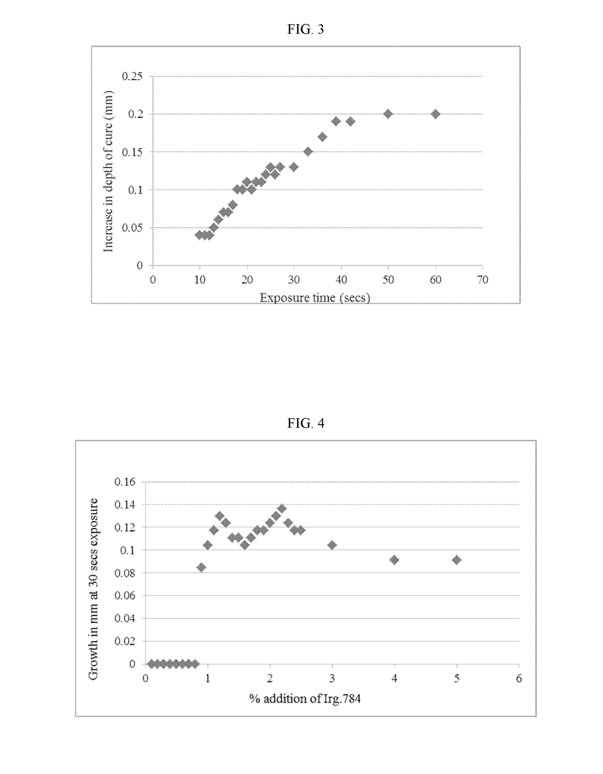
ase of Depth of Cure with Increased Exposure Time

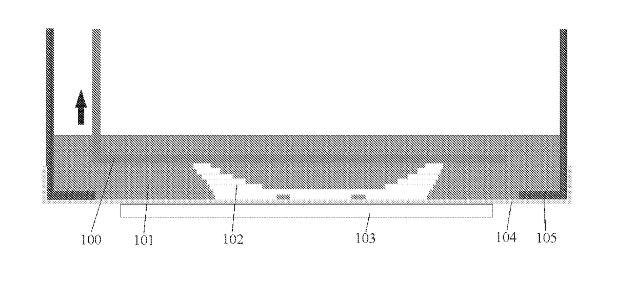
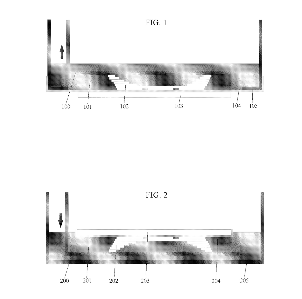
[0127]In this experiment the LCD screen used in the Liquid Crystal 3D printer was a 7″ rear view reversing display screen, known as screen D. This screen had a manufacturer's quoted brightness of 250 candela, however it was measured at 197 candela using a Konica Minolta LS110 luminance meter, by turning the screen on to show a completely white display and holding the meter on the screen in a darkened room. The screen had 800×480 pixels generating 133 pixels per inch (PPI). The image was sent from the computer to the screen via a video graphics array (VGA) input.

[0128]The standard daylight procedure described earlier was used. The print platform was removed after the required set of exposure cycles and the thickness of layer created was measured. The exposure time was adjusted and the results are shown in Table 2 and graphically in FIG. 3.

TABLE 2the amount of polymer growth with increasedtime using the Formulation A.TimeThickness(sec)(...

example 2

g the Addition of Irg.784

[0130]To investigate how the rate of cure is influenced by the level of Irg.784, the standard formulation without any Irg.784 was taken. To it was added 0.1% addition of Irg.784 and then this was separately increased by 0.1% increments. The mixtures were stirred in a glass vessel for 60 minutes at 60° C. and left to stand for 24 hours to allow all the air to either break the surface or be absorbed. This process was used for all future raw material additions. The formulations were tested for growth at various exposure times in the Liquid Crystal 3D printer with screen D inserted as the imaging source using the standard procedure described earlier. The results are laid out in Table 3 and shown graphically in FIG. 4.

TABLE 3the amount of growth at 30 seconds exposurewith different % additions of Irg.784.% additionalGrowth with 30of Irg 784secs exposure0.10.000.20.000.30.000.40.000.50.000.60.000.70.000.80.080.90.1010.121.10.131.20.121.30.111.40.111.50.101.60.111....

example 3

t of Increased Time with Different % Additions of Irg.784

[0132]The standard formulation was used, but with the concentration of Irg.784 set at three levels 1.1%, 2.1% and 3.1%. They were tested for rate of growth at various exposure times in the Liquid Crystal 3D printer with screen D inserted as the imaging source using the standard procedure described earlier. The rate of growth at different exposure times was determined at these concentrations. The results are laid out in Table 4 and shown graphically in FIG. 5.

TABLE 4Growth in mm of polymer at different exposuretimes with different % of Irg.784Time(secs)1.1% 7842.1% 7843.1% 7847.50.000.000.0010.00.000.040.0312.50.040.070.0515.00.090.090.0717.50.100.100.0820.00.120.110.0922.50.130.120.0925.00.150.130.0927.50.190.140.1030.00.200.140.1132.50.210.160.1335.00.220.160.14

[0133]It was found that at the lowest 1.1% Irg.784 level the required time to initiate growth is longer than for the higher concentrations, as would be expected. What ...


PUM

PropertyMeasurementUnit
Luminescenceaaaaaaaaaa
Shrinkageaaaaaaaaaa

Abstract

The present invention relates to formulations for use in 3-D printing using radiation from visual display screens. The formulations comprise titanocene photoinitators and co-initiators. The invention also relates to methods of forming 3-D objects using said formulations.

Description

FIELD OF THE INVENTION[0001]This invention relates to polymer resin formulations for use in making 3D images. The formulations comprise titanocene photoinitators and co-initiators. This invention also relates to a method for making a three dimensional (3D) image by additive manufacturing or 3D printing. Specifically it describes formulations and techniques that optimise the speed of printing, resolution of image and properties of the finished objects in 3D printed objects created by daylight emitting liquid crystal display (LCD) screens.BACKGROUND OF THE INVENTION[0002]This invention lies in the field of 3D printing, also known as rapid prototyping or additive manufacturing. It is a method of creating three dimensional objects in layers each obtained from a digital representation of the object. Typically an object is scanned in 3 dimensions or generated digitally by computer-aided design (CAD) and split into layers of a pre-determined thickness. These layers are sequentially sent to...

Claims


Application Information

Patent Timeline
IPC IPC(8): C08L75/14B33Y70/00B33Y10/00B29C64/129
CPCC08L75/14B33Y70/00B33Y10/00B29C64/129B33Y30/00B29C64/264B29K2995/0026B29K2871/00B29K2827/12B29K2033/08G03F7/0037G03F7/027G03F7/029B33Y80/00B29C64/255B29C64/20B29C64/176B29C64/307B33Y50/00B29C64/205B29C64/30B29C64/40B29C64/182B33Y40/00B33Y40/20B29C64/00B29C64/245B33Y40/10B29C64/227B29C64/10B29C64/25B33Y99/00
Inventor HOLT, PAUL
Owner PHOTOCENTRIC
Why Eureka
Try Eureka