Evaporation apparatus

An evaporation device and evaporation source technology, applied in vacuum evaporation plating, ion implantation plating, coating and other directions, can solve the problems of complex and expensive devices

Inactive Publication Date: 2010-06-16
WONIK IPS CO LTD
View PDF0 Cites 5 Cited by
  • Summary
  • Abstract
  • Description
  • Claims
  • Application Information

AI Technical Summary

Problems solved by technology

However, this device becomes complex and expensive since it req

Method used


Image

  • Evaporation apparatus
  • Evaporation apparatus
  • Evaporation apparatus

Examples


Embodiment Construction

[0019] Hereinafter, exemplary embodiments of the present invention will be described in detail with reference to the accompanying drawings.

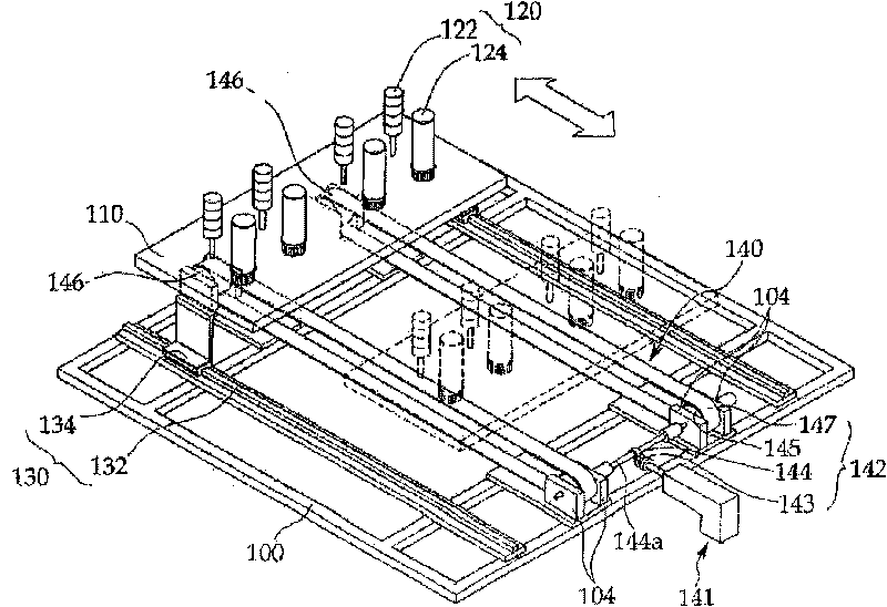
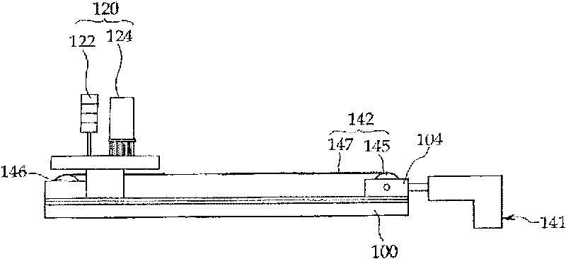
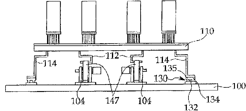
[0020] refer to Figure 1 to Figure 3 , the evaporation device according to the embodiment of the present invention includes a frame body 100, a moving plate 110 installed on the frame body 100 in a linearly reciprocating manner on the frame body 100, a plurality of evaporation sources 120 arranged on the moving plate 110, and The guide unit 130 for guiding the moving plate 110 to move linearly, and the driving unit 140 for linearly reciprocating moving the moving plate 110 .

[0021] The moving plate 110 is used to carry and move a plurality of evaporation sources 120 together, and has a top surface on which the plurality of evaporation sources 120 are disposed and a mounting plate for connecting the moving plate 110 to the driving unit 140 is arranged thereon. The bottom surface of the pair of connection parts 112 . In addition, a pa...


PUM


Abstract

Disclosed is an evaporation apparatus, which includes a moving plate disposed on the frame to be reciprocated, a plurality of evaporation sources for evaporating an evaporation material onto a substrate so as to deposit the evaporation material on the substrate in which the plurality of evaporation sources is arranged in a direction intersecting a movement direction of the moving plate on the moving plate, and a driving unit for reciprocating the moving plate. The evaporation apparatus can be simplified in structure, and can deposit the evaporation material with a uniform thickness on the substrate in a short time.

Description

technical field [0001] The present invention relates to an evaporation apparatus, and more particularly, to an evaporation apparatus that deposits an evaporation material with a uniform thickness on a large-sized substrate while having a simplified structure. Background technique [0002] Generally, an evaporation apparatus deposits a material filled in an evaporation source on a substrate by heating and evaporating a material filled in an evaporation source in a vacuum chamber that is evacuated and decompressed with a vacuum pump. [0003] Recently, there has been an increasing need to provide an evaporation apparatus capable of depositing an evaporation material on a substrate in a short time. As an example of an evaporation device, an evaporation device having a large-sized evaporation source having an elongated opening whose width is equal to that of the substrate and performing evaporation processing while moving a substrate has been developed. In such an apparatus, th...

Claims


Application Information

Patent Timeline
IPC IPC(8): H01L21/20
CPCC23C14/24
Inventor 权真焕宋校俊赵成在朴基柱李炫基睦镇一
Owner WONIK IPS CO LTD
Why Eureka
Try Eureka