Chain link woven mesh with double knot

A technology for weaving nets and chain links, applied in the direction of knitting, warp knitting, wire netting, etc., can solve the problems of single knot, loose standard and so on

Inactive Publication Date: 2010-12-08
NV BEKAERT SA
View PDF3 Cites 6 Cited by
  • Summary
  • Abstract
  • Description
  • Claims
  • Application Information

AI Technical Summary

Problems solved by technology

[0006] The object of the present invention is to provide an improved chain-link braided net, t

Method used


Image

  • Chain link woven mesh with double knot
  • Chain link woven mesh with double knot

Examples


Embodiment Construction

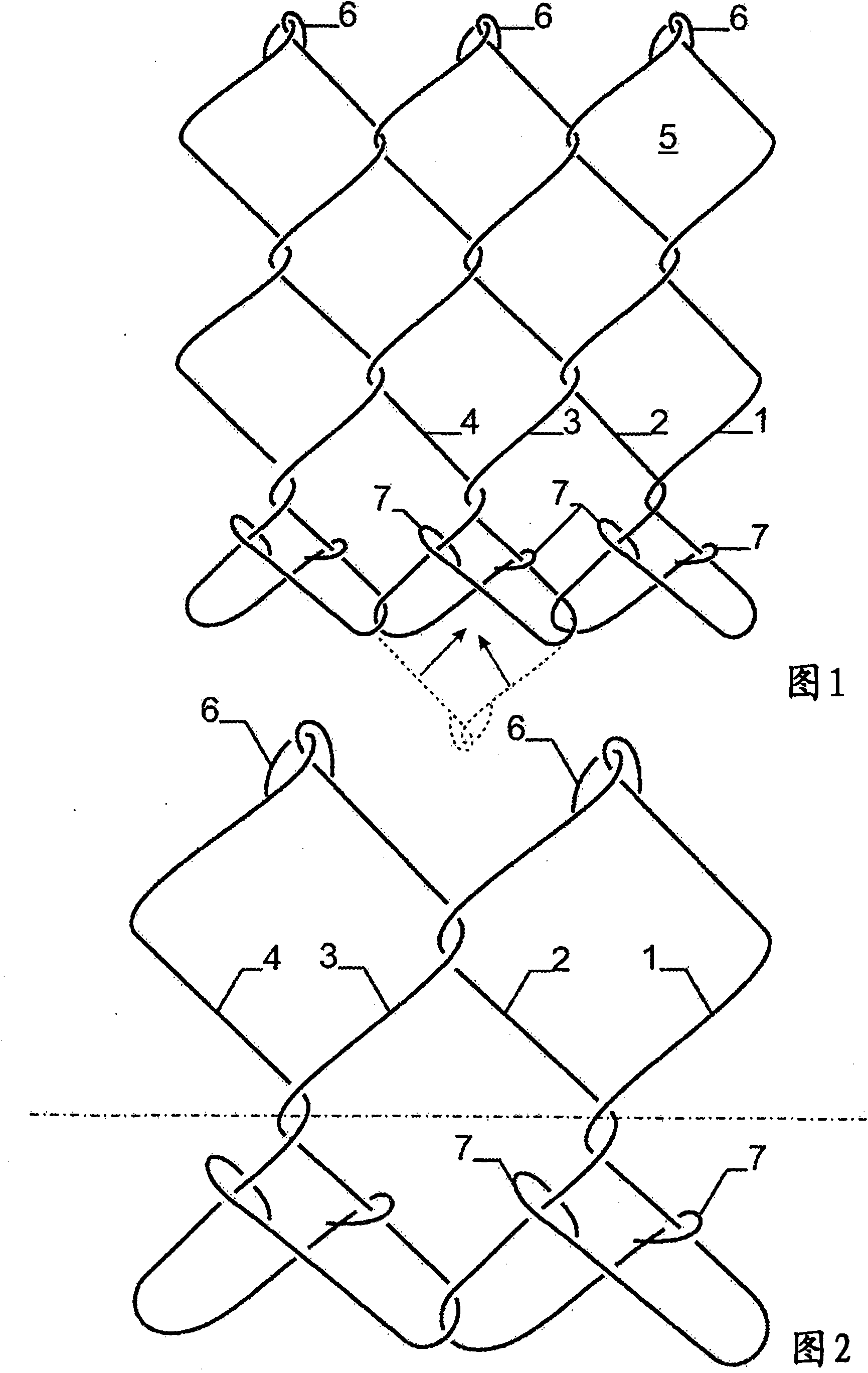
[0014] figure 1 A top view of a portion of a chain-link braided mesh according to the invention is shown in a normal unfolded state. The braided mesh comprises successive undulating or zigzag transverse links 1 , 2; 3, 4; . . . , which are interconnected or interwoven at the bends of the links. Each pair of consecutive wavy links 1, 2; 3, 4; . . . forms a row of adjacent rectangular or square meshes 5 with four sides. The straight sides of the mesh 5 between the bends may be corrugated. Each chain link 1, 2, 3, 4... is formed, for example, by helically winding a steel wire around a steel rod with a substantially rectangular cross-section. This means that the wire has been bent into a zigzag pattern. Each link or wire is threaded across the width of the braid into a previously strung zigzag wire link. Steel wires or chain links may suitably be coated with an anti-corrosion coating. Examples of such nets are clearly described in, for example, US Patents 3,473,652 and 3,512,...


PUM


Abstract

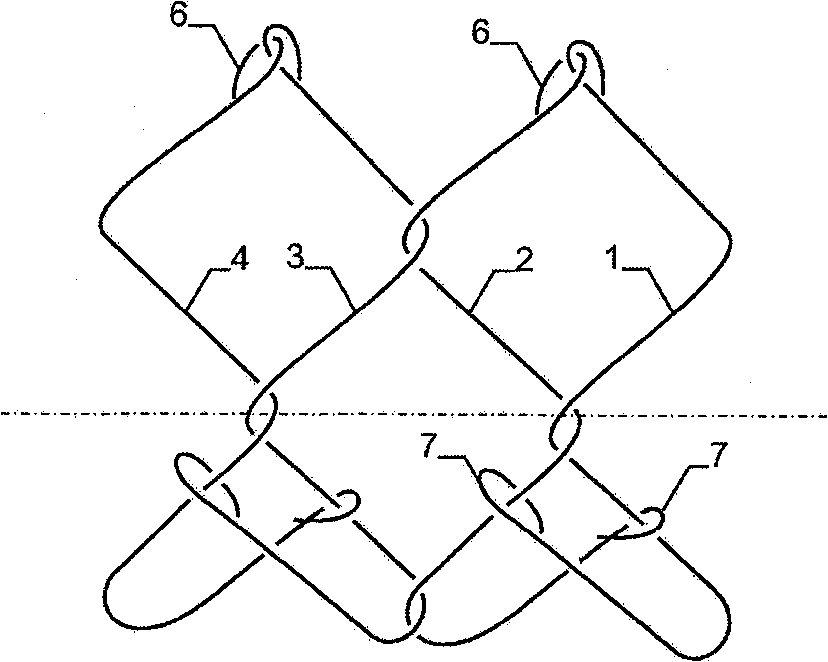
A chain link woven mesh comprises successive undulated transverse links (1,2,3,4), which are interconnected together at the bent portions of the links, whereby each pair of successive undulated links (1,2), (3,4) forms a row of adjacent rectangular or square meshes (5) with four sides. At least at one border of the mesh, for each pair of successive links, the last side of the first link (1) is bent upwardly and backwardly over a sharp angle, whereby the end of this last side is hooked around the penultimate (last but one) side of the second link (2). The last side of the second link (2) is bent downwardly and backwardly over a sharp angle, whereby the end of this last side is hooked around the penultimate (last but one) side of the first link (1). The advantage is that a very strong border is obtained.

Description

technical field [0001] The present invention relates to a chain-link braided mesh comprising continuous undulating or zigzag transverse links which are interconnected at the bends of the links so that each pair of consecutive undulating links forms a row Adjacent rectangular or square meshes with four sides. Background technique [0002] The aforementioned chain-link braided meshes are generally known and described, for example, in US Patents 3473652, 3512760 and European Patent 862959B1. [0003] Such known chain-link braided nets are usually provided with standard single knots at both edges or edges. A standard single knot is made or obtained by hooking the ends of each pair of consecutive links over each other. [0004] A disadvantage of this known chain-link woven netting provided with standard single knots is that these standard single knots do not close in a secure manner, or open under rather low tension. This is a practical problem for the successful use of this k...

Claims


Application Information

Patent Timeline
IPC IPC(8): E04H17/04B21F27/00B21F27/02E21D11/15D04B21/12
CPCB21F29/00E04H17/04D04C1/08E04H17/05
Inventor G·A·维达尔·鲁德洛夫C·阿库尼亚·马丁内斯H·帕雷德斯·蒙特西诺斯
Owner NV BEKAERT SA
Why Eureka
Try Eureka