Coating apparatus
A coating device and coating technology, applied in the direction of the device for coating liquid on the surface, spraying device, lighting device, etc.
- Summary
- Abstract
- Description
- Claims
- Application Information
AI Technical Summary
Problems solved by technology
Method used
Image
Examples
no. 1 approach
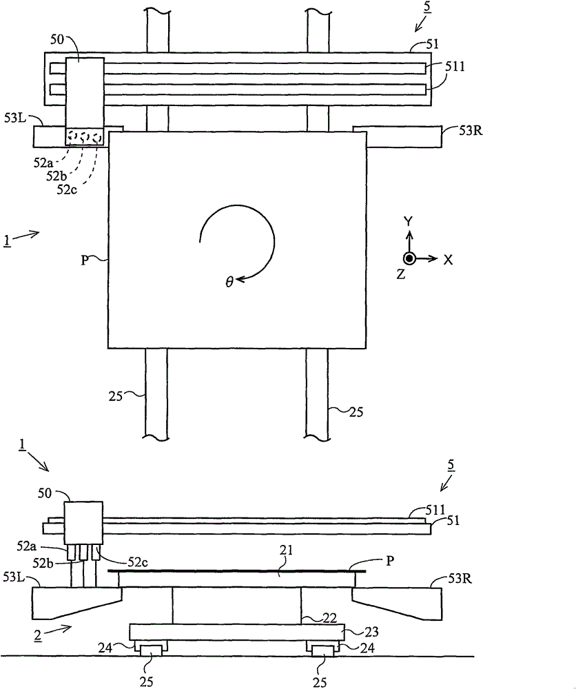
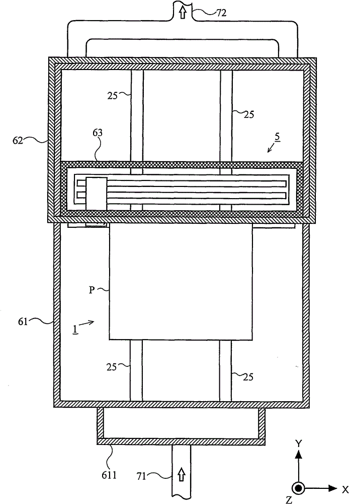
[0170] Next, a coating device 1 according to a first embodiment of the present invention will be described with reference to the drawings. The first embodiment is a coating device 1 in which an exhaust pipe is not provided in a chamber space but an exhaust pipe is provided in a box space or a slide space. In addition, description is omitted about the outline|summary of the coating apparatus 1, and it demonstrates mainly about the connection part of the supply pipe and the exhaust pipe which are the characteristics of 1st Embodiment. also, Figure 11 It is a schematic diagram showing a first example of a flow of nitrogen gas in the coating device 1 of the first embodiment. Figure 12 It is a schematic diagram which shows the 2nd example of the flow of nitrogen gas in the coating apparatus 1 of 1st Embodiment. Figure 13 It is a schematic diagram which shows the 3rd example of the flow of nitrogen gas in the coating apparatus 1 of 1st Embodiment. Figure 14 It is a schematic ...
no. 2 approach
[0180] Next, a coating device 1 according to a second embodiment of the present invention will be described with reference to the drawings. The second embodiment is a coating device 1 in which exhaust pipes are not provided in the chamber space, but exhaust pipes are respectively provided in the box space and the slide space. In addition, description is omitted about the outline|summary of the coating apparatus 1, and it demonstrates mainly about the connection part of the supply pipe and the exhaust pipe which are the characteristics of 2nd Embodiment. also, Figure 15 It is a schematic diagram showing the first example of the flow of nitrogen gas in the coating device 1 of the second embodiment. Figure 16 It is a schematic diagram which shows the 2nd example of the flow of nitrogen gas in the coating apparatus 1 of 2nd Embodiment. Figure 17 It is a schematic diagram which shows the 3rd example of the flow of nitrogen gas in the coating apparatus 1 of 2nd Embodiment. In ...
no. 3 approach
[0188] Next, a coating device 1 according to a third embodiment of the present invention will be described with reference to the drawings. The third embodiment is a coating device 1 in which an exhaust pipe is provided in a chamber space, and an exhaust pipe is provided in a box space or a sliding space. In addition, description is omitted about the outline|summary of the coating apparatus 1, and it demonstrates mainly about the connection part of the supply pipe and the exhaust pipe which are the characteristics of 3rd Embodiment. also, Figure 18 It is a schematic diagram showing the first example of the flow of nitrogen gas in the coating apparatus 1 of the third embodiment. Figure 19 It is a schematic diagram showing the second example of the flow of nitrogen gas in the coating apparatus 1 of the third embodiment. Figure 20 It is a schematic diagram which shows the 3rd example of the flow of nitrogen gas in the coating apparatus 1 of 2nd Embodiment. In addition, in ...
PUM
 Abstract
Description
Claims
Application Information
 - R&D
- Intellectual Property
- Life Sciences
- Materials
- Tech Scout
- Unparalleled Data Quality
- Higher Quality Content
- 60% Fewer Hallucinations
Browse by: Latest US Patents, China's latest patents, Technical Efficacy Thesaurus, Application Domain, Technology Topic, Popular Technical Reports.
© 2025 PatSnap. All rights reserved.Legal|Privacy policy|Modern Slavery Act Transparency Statement|Sitemap|About US| Contact US: help@patsnap.com


