Steam heater circular heating method

A technology of steam heater and circulation heating, which is applied in the direction of metal processing equipment, engine lubrication, workpiece surface treatment equipment, etc. It can solve the problems of unable to take protective measures, violent vibration of pipeline support, leakage of pneumatic shut-off valve, etc., to prevent local If the temperature of the process medium is too high or cause system safety hazards, improve the heating efficiency and prevent the effect of overheating

Active Publication Date: 2012-02-08
BAOSTEEL ENG & TECH GRP
View PDF0 Cites 0 Cited by
  • Summary
  • Abstract
  • Description
  • Claims
  • Application Information

AI Technical Summary

Problems solved by technology

[0005] When the temperature of the emulsion in the main liquid supply tank is greater than the T2 value, according to the control requirements, the pneumatic shut-off valve is closed and the steam heater stops heating, but there may be leakage when the pneumatic shut-off valve is closed. When the pneumatic shut-off valve leaks If the circulating heating pump is running normally, the temperature of the emulsion in the liquid supply main tank will continue to rise, exceeding the required T2 value, and until the temperature alarms, the manual valves before and after the pneumatic shut-off valve must be manually closed to slow down the temperature rising trend. The increase in temperature affects the quality of the emulsion, thereby affecting the quality of the strip product
[0006] When the pneumatic shut-off valve is automatically closed according to the control requirements, the pneumatic shut-off valve leaks and the circulating heating pump stops running due to failure or other reasons (that is, the steam heater and its pipeline are filled with emulsion and are in a static state). In this case, the leaked steam heats the heater and the emulsion in the inlet and outlet pipes. As the temperature of the static emulsion becomes higher and higher, a physical change of gasification will eventually occur. With further leakage of steam, gasification The area of ​​the closed pipeline is getting bigger and bigger, causing the emulsion in the pipeline to start to gasify. At this time, this part of the emulsion has been completely damaged. At the same time, the emulsion in the closed pipeline is gasified, causing the pipeline to expand and stretch violently. The bracket vibrates violently. Under normal circumstances, most of the pipeline bracket is welded on the main tank of the emulsion supply and the overall steel structure platform. The vibration of the pipeline drives the vibration of the main tank of the liquid supply and the overall steel structure platform, forming a potential safety hazard.
[0007] As the heater runs longer, scaling or even blockage will occur on the emulsion side of the tubular steam heater, which will easily cause the circulating heating pump to hold the pump, cause the motor to overheat, and damage the equipment. This cannot be detected in the conventional circulating heating system. Due to this change, corresponding protection measures cannot be taken

Method used


Image

  • Steam heater circular heating method
  • Steam heater circular heating method
  • Steam heater circular heating method

Examples


Embodiment Construction

[0032] The present invention will be described in detail below in conjunction with the accompanying drawings and embodiments.

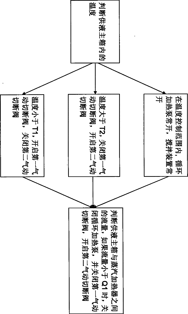
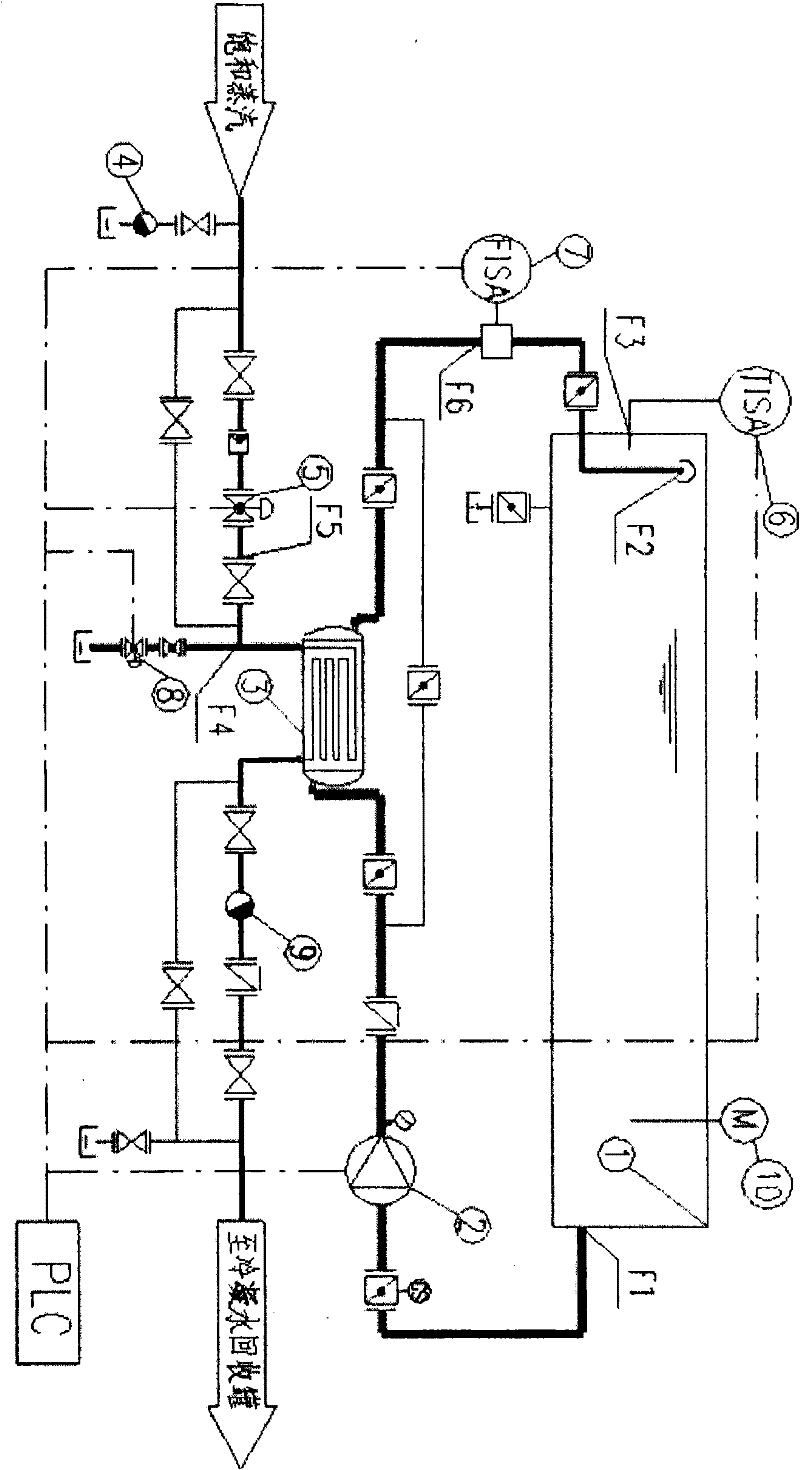
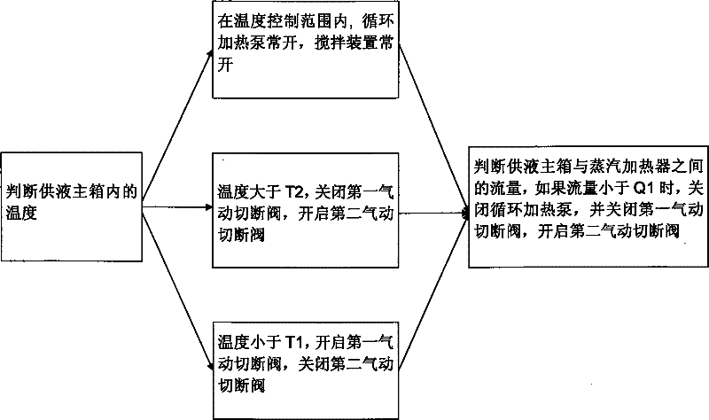
[0033] see first figure 2 , is a steam heater circulating heating system, mainly composed of a liquid supply main tank 1, a circulating heating pump 2, a steam heater 3, a steam trap 4, a first pneumatic shut-off valve 5, a temperature sensor 6, a flow sensor 7, a second Pneumatic cut-off valve 8, steam trap 9, stirring device 10 and other components.

[0034] A stirring device 10 is housed in the liquid supply main tank 1 . The two ends of the liquid supply main tank 1 are respectively connected to the steam heater 3 through pipelines, and a circulating heat pump 2 is arranged between the steam heater 3 and the liquid supply main tank 1 . One end of the steam heater 3 is connected to the saturated steam pipe, and the other end of the steam heater 3 is connected to the condensed water recovery tank. A flow sensor 7 is installed on the pipeline bet...


PUM


Abstract

The invention relates to a steam heater circular heating method, which is used for circularly heating a circular heating system of the steam heater. The system comprises a liquid supply main box, a circular heating pump, the steam heater, pneumatic stop valves and a temperature sensor, and is controlled by a PLC in an interconnected manner. When the circular heating method is adopted, the temperature control range is set as from T1 to T2 ( T2 is more than T1) and a flow control lower limit is Q1. The method comprises the following steps: A, determining the temperature in the liquid supply main tank, wherein a step B is executed if the temperature is within the temperature control range, a step C is executed if the temperature is above T2, and a step D is executed when the temperature is below T1; B, if the circular heating pump is normally open and a stirring device is normally open, executing a step E; C and D, opening and closing a first pneumatic stop valve, opening and closing a second pneumatic stop valve, and executing the step E; and E, determining the flow between the liquid supply main tank and the steam heater. When the method of the invention is adopted, the circular heating efficiency of emulsion is improved, safety is improved, and the operation is convenient and easy.

Description

technical field [0001] The invention relates to an emulsion system of a cold tandem rolling mill and an alkaline cleaning circulation system of a cold rolling mill, in particular to an improved circulation heating method of a steam heater. Background technique [0002] In the emulsion circulation system of the rolling mill, temperature control is very important. In order to ensure that the temperature in the emulsion supply main tank is controlled within the range required by the oil product (set from T1 to T2, T2 > T1), the emulsion of the rolling mill adopts The circulation heating method is the heating of the liquid supply main tank. [0003] Emulsion circulating heating refers to a method of installing circulating heating pumps, steam heaters, pneumatic shut-off valves, temperature sensors and other devices next to the emulsion supply main tank. The whole heating process is that the circulating heating pump pumps from one side of the main liquid supply tank, lifts th...

Claims


Application Information

Patent Timeline
Patent Type & Authority Patents(China)
IPC IPC(8): B21B28/00B21B45/02F16N39/04
Inventor 刘兴祥周光升周玉军潘仲任明华
Owner BAOSTEEL ENG & TECH GRP
Why Eureka
Try Eureka