Rotary drilling rig and wire rope guiding device thereof

A technology of guiding device and rotary drilling rig, which is applied in the direction of rotary drilling rig, hoisting device, rotary drilling, etc., and can solve the problem of large deflection angle γ of steel wire rope 3′, wear and tear of steel wire rope 3′, and the effect of reduction is not obvious, etc. problem, achieve the effect of reducing wear, prolonging service life and reducing deflection angle

Inactive Publication Date: 2010-12-15
BEIJING SANY HEAVY MASCH CO LTD
View PDF5 Cites 21 Cited by
  • Summary
  • Abstract
  • Description
  • Claims
  • Application Information

AI Technical Summary

Problems solved by technology

[0007] Setting the guide pulley 4'2 on the mast 1' can improve the stress of the mast 1', but it brings a new problem: because the axial length of the single-layer winding reel 2' is longer, the wire rope 3' will When the two axial ends of the cylinder 2' are wound, such as Figure 4 and Figure 5 As shown, the deflection angle γ of the steel wire rope 3' relative to the guide pulley 4'2 is too large, causing friction between the steel wire rope 3' and the guide pulley 4'2, resulting in serious wear of the steel wire rop...

Method used


Image

  • Rotary drilling rig and wire rope guiding device thereof
  • Rotary drilling rig and wire rope guiding device thereof
  • Rotary drilling rig and wire rope guiding device thereof

Examples


Embodiment Construction

[0042] The core of the present invention is to provide a wire rope guiding device, which can significantly reduce the deflection angle of the wire rope, thereby reducing the wear of the wire rope and prolonging its service life. In addition, another core of the present invention is to provide a rotary drilling rig comprising the above-mentioned wire rope guide device.

[0043] In order to enable those skilled in the art to better understand the technical solutions of the present invention, the present invention will be further described in detail below in conjunction with the accompanying drawings and specific embodiments.

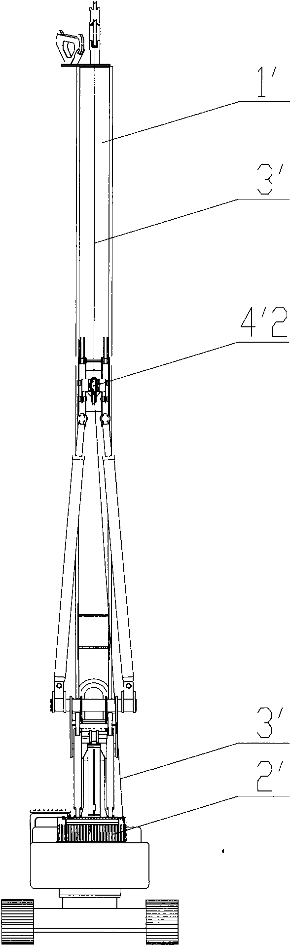
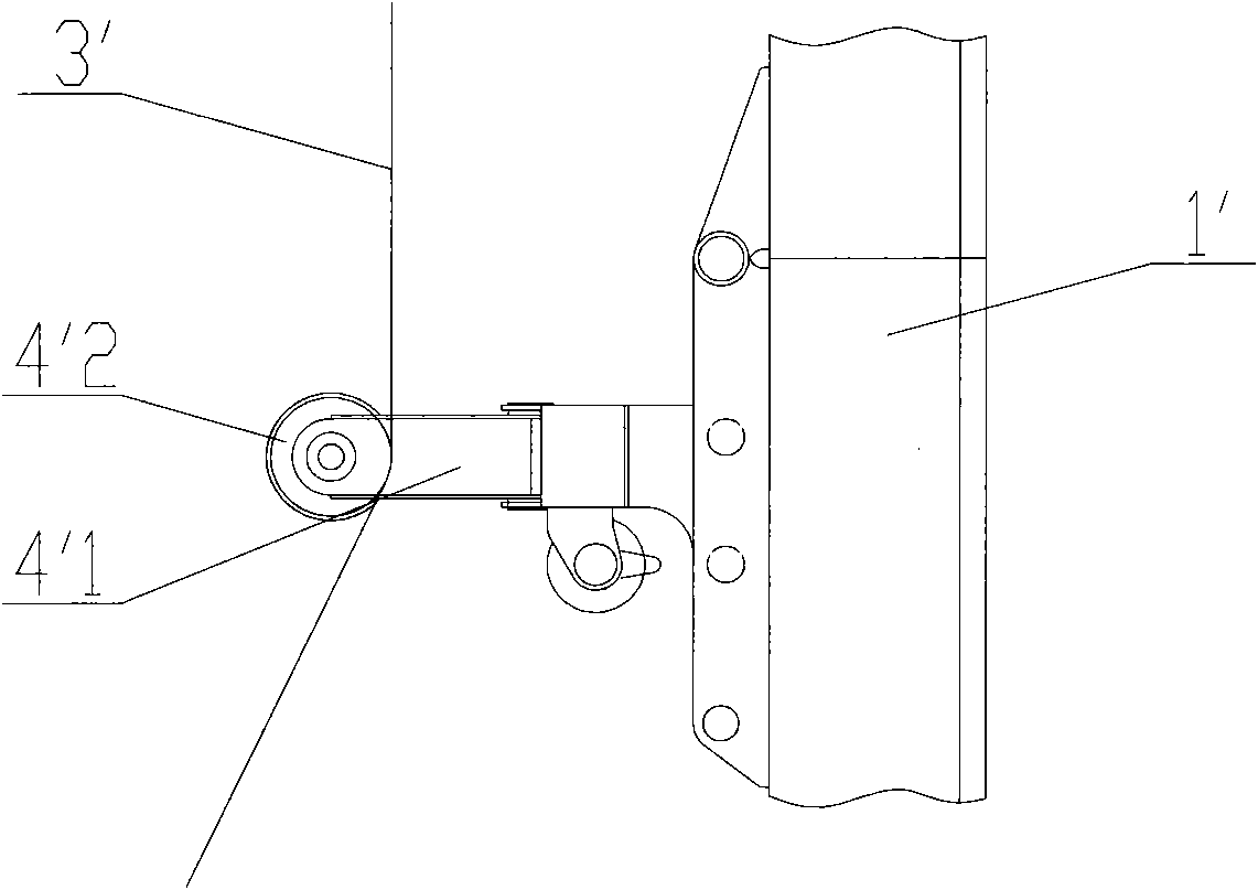
[0044] Please refer to Image 6 , Figure 7 and Figure 8 , Image 6 It is a schematic diagram of the structure of the wire rope guiding device connected to the mast in an embodiment of the present invention; Figure 7 for Image 6 Side view of the medium wire rope guide; Figure 8 for Image 6 Schematic diagram of the structure of the guide pulley ro...


PUM


Abstract

The invention discloses a wire rope guiding device, which comprises a swing frame (41) that is rotatably connected on a mast (1) of a rotary drilling rig so that the swing frame (41) can swing towards the left side and the right side of the mast (1); a front end part of the swing frame (41) is provided with a guide pulley (42),and a wire rope (3) bypasses the guide pulley (42) and is then wound on a winding drum of the rotary drilling rig; and the guide pulley (42) is further rotatably connected with the swing frame (41) so that the guide pulley (42) can rotate under the driving of the axial force of the wire rope (3) along the guide pulley (42). The device can reduce the drift angle of the wire rope (3) obviously, thus reducing the wear of the wire rope (3) and prolonging the service life thereof. Moreover, the invention also discloses the rotary drilling rig comprising the wire rope guiding device.

Description

technical field [0001] The invention relates to the technical field of rotary drilling rigs, in particular to a wire rope guiding device for rotary drilling rigs. Furthermore, the present invention also relates to a rotary drilling machine comprising the wire rope guide device. Background technique [0002] With the rapid development of my country's infrastructure construction, the demand for pile machinery, especially rotary drilling rigs, is also increasing. [0003] Please refer to figure 1 and figure 2 , figure 1 It is a structural schematic diagram of a typical rotary drilling rig in the prior art; figure 2 for figure 1 Side view of a rotary drilling rig. [0004] At present, there are two ways to install the main winch of the rotary drilling rig in the prior art: one is to install the main winch on the mast, and use a multi-layer winding drum. This installation method is suitable for deeper drilling. Shallow, compact rotary drilling rigs; such as figure 1 and...

Claims


Application Information

Patent Timeline
IPC IPC(8): B66D1/36E21B3/06
CPCB66D1/38
Inventor 龚高柏张世平
Owner BEIJING SANY HEAVY MASCH CO LTD
Why Eureka
Try Eureka