Sinusoidal gas micro-pressure generator

A generator and micro-pressure technology, applied in the direction of measuring fluid pressure, instruments, measuring devices, etc., can solve the problems of limited use of detection sensors, large waveform distortion rate, and small sinusoidal pressure, etc., and achieve simple structure, small waveform distortion, and easy Effects of Frequency and Amplitude

Inactive Publication Date: 2010-12-15
HEBEI UNIV OF TECH
View PDF5 Cites 17 Cited by
  • Summary
  • Abstract
  • Description
  • Claims
  • Application Information

AI Technical Summary

Problems solved by technology

Its main disadvantages are: because the magnetic liquid pushes the water pressure to generate liquid sinusoidal pressure, the damping effect of water is relatively obvious, the generated sinusoidal pressure is relatively small, and the waveform distortion rate is relatively large; at the same time, because the medium directly contacted by the pressure sensor probe is water, Therefore, the use of detection sensors is greatly limited

Method used


Image

  • Sinusoidal gas micro-pressure generator
  • Sinusoidal gas micro-pressure generator
  • Sinusoidal gas micro-pressure generator

Examples


Embodiment Construction

[0015] Further describe the present invention below in conjunction with embodiment and accompanying drawing thereof:

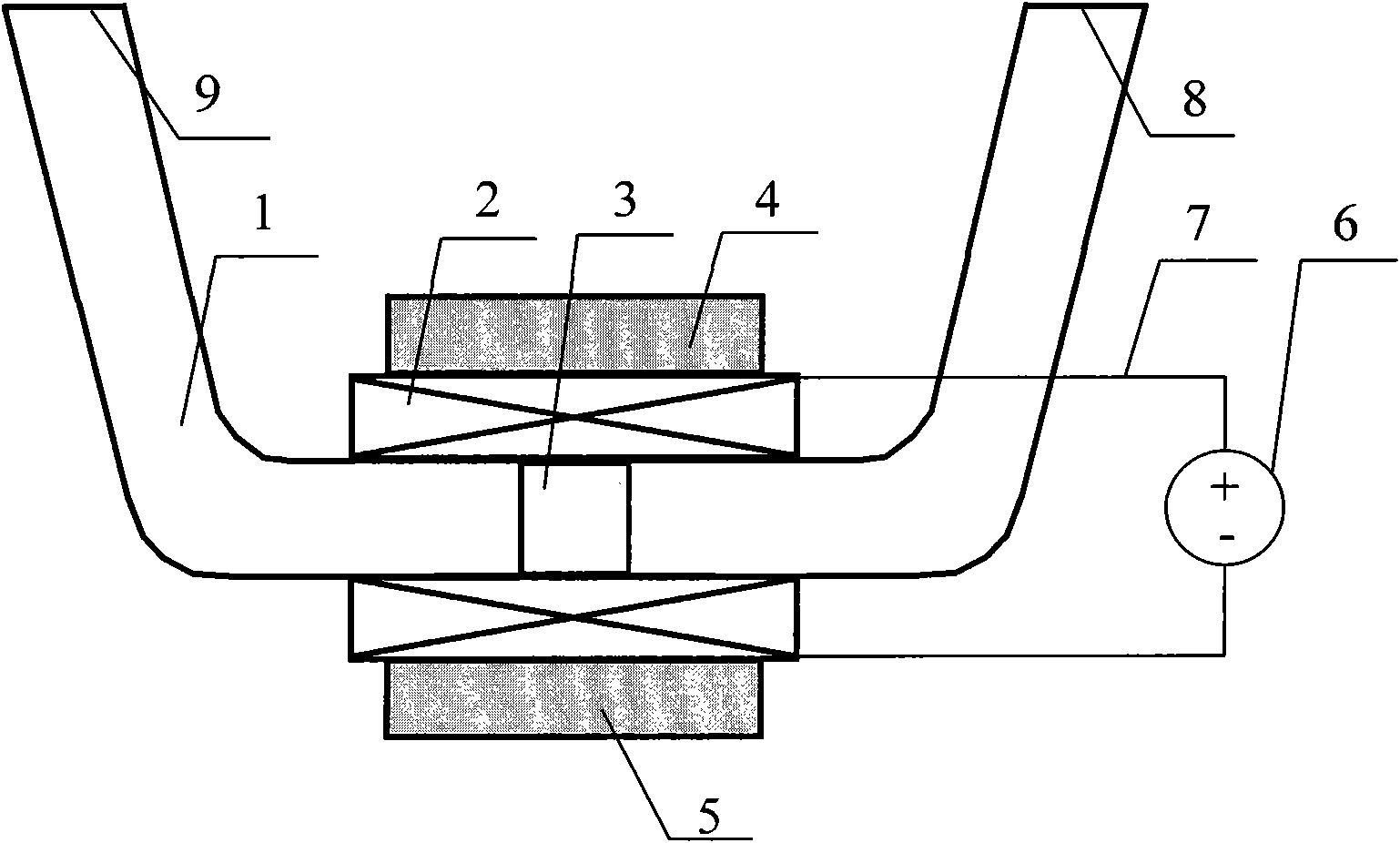
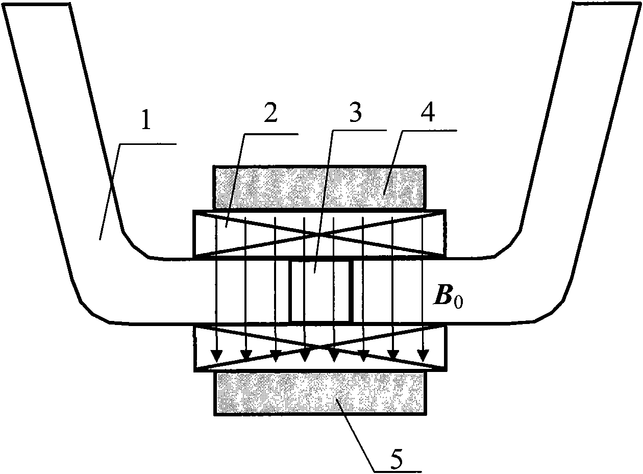
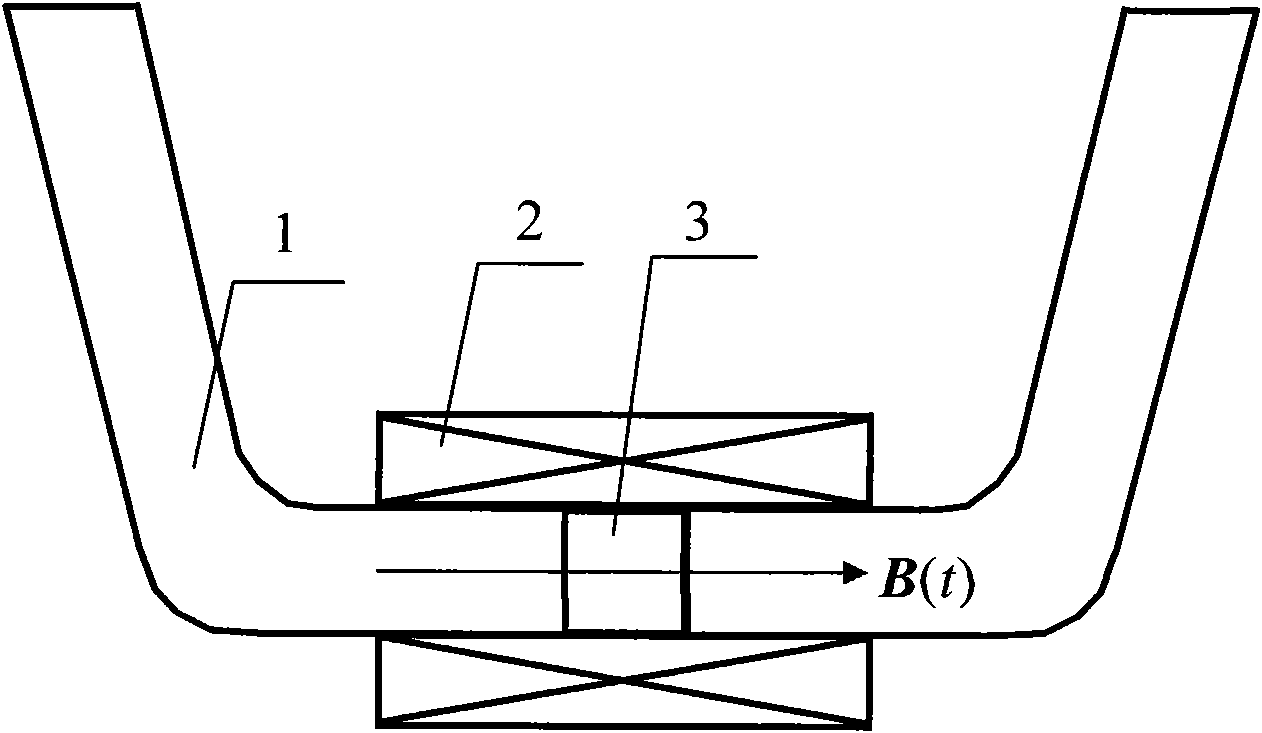
[0016] The sinusoidal gas micro-pressure generator (abbreviation generator, referring to Figure 1-8 ), it is characterized in that the generator comprises a U-shaped tube 1, an excitation coil 2 is set on the bottom of the U-shaped tube 1, an upper permanent magnet 4 is installed on the excitation coil 2, and a lower permanent magnet 4 is installed on the excitation coil 2. The permanent magnet 5 and the excitation coil 2 are connected to the AC power supply 6 through the wire 7; the bottom tube of the U-shaped tube 1 is equipped with a magnetic liquid 3, and the magnetic liquid 3 is radially filled in the U-shaped tube under the action of the magnetic field force of the permanent magnet 1 bottom pipe diameter.

[0017] The working principle of the present invention is: the magnetic liquid 3 loaded in the bottom tube of the U-shaped tube 1 needs to fill the ...


PUM


Abstract

The invention discloses a sinusoidal gas micro-pressure generator. The generator is characterized by comprising a U-shaped tube, wherein an excitation coil is sleeved outside the bottom tube of the U-shaped tube; an upper permanent magnet is arranged above the excitation coil, while a lower permanent magnet is arranged under the excitation coil, and the excitation coil is connected with an alternating current power supply through a lead wire; and magnetic fluid is filled in the bottom tube of the U-shaped tube, and is full of the bottom tube diameter of the U-shaped tube under the action of the magnetic force of the permanent magnets. The generator has the advantages of low waveform deviation factor, simple structure and easy control.

Description

technical field [0001] The invention relates to a gas pressure generator, in particular to a magnetic liquid-based sinusoidal gas micro-pressure generator. Background technique [0002] Existing gas pressure generators mainly include outlet-modulated sinusoidal pressure generators, standing-wave tube-type pressure oscillators, cavity-adjustable pressure generators, etc., all of which control the waveform change of the output pressure through mechanical movement, but Its waveform distortion rate is relatively large, and the structure is complex, the cost is high, and it is difficult to control the waveform and amplitude. [0003] Existing magnetic liquid sinusoidal pressure generator (referring to literature: B. Dynamic calibration of manometer systems, Medical and Biological Engineering, 1976.3 (Dynamic calibration of manometer systems, Medicine and Bioengineering) is a device used in medical experiments, a source of pressure signals output through solid media. Its struct...

Claims


Application Information

Patent Timeline
Patent Type & Authority Applications(China)
IPC IPC(8): G01L27/00
Inventor 杨文荣杨庆新
Owner HEBEI UNIV OF TECH
Why Eureka
Try Eureka