Releasing device

A technology of releasing device and locking lever, which can be applied to measuring devices, instruments, scientific instruments, etc., can solve problems such as danger, and achieve the effect of compact structure, flexible release action and small size

Inactive Publication Date: 2011-12-21
天津陆海石油设备系统工程有限责任公司
View PDF0 Cites 0 Cited by
  • Summary
  • Abstract
  • Description
  • Claims
  • Application Information

AI Technical Summary

Problems solved by technology

When the test piece is too large, such as: hundreds of kilograms or more than one ton, this operation becomes very dangerous

Method used


Image

  • Releasing device
  • Releasing device
  • Releasing device

Examples


Embodiment Construction

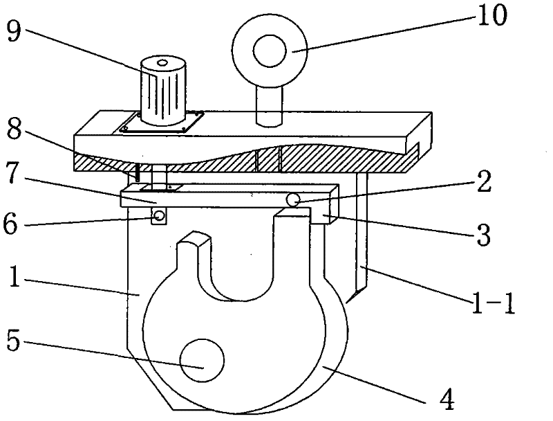
[0018] Such as Figure 1-10 As shown, a release device includes a motor 9, an optical sensor 8, and also includes a hook body 1, a locking rod nail 2, a locking rod 3, a hook 4, a hook nail 5, an electric pin 6, a motor rod 7 and Suspension rod or suspension ring 10, three optical sensors 8 are arranged in hook body 1 respectively.

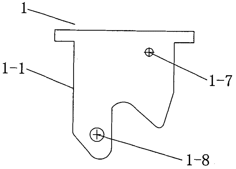
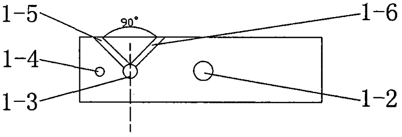
[0019] The hook body 1 is a T-shaped body, the upper end is a rectangular entity, and the lower end is two symmetrical side walls 1-1 with a V-shaped opening connected to the upper end. There is a distance between the two side walls 1-1. The upper end surface of the hook body 1 is respectively provided with a screw hole 1-2, a motor rod through hole 1-3, a lock sensor through hole 1-4, an opening sensor groove 1-5, and a closing sensor groove 1-6. The two measuring walls 1-1 are respectively symmetrically provided with locking rod nailing holes 1-7 and hook nailing holes 1-8.

[0020] The opening sensor groove 1-5, the closing sensor groove 1-6 ...


PUM


Abstract

The invention relates to a releasing device for finishing impact drop tests of a dangerous goods transport packaging container. Three optical sensors are respectively arranged in a hook body, a motor and a suspender or a swinging ring are respectively fixed on the upper end surface of the hook body, a locking rod is arranged between two side walls on the hook body through a locking rod drift bolt, the locking rod drift bolt and the locking rod are in clearance fit, a motor rod connected with the motor passes through the upper end of the hook body and extends out of the locking rod body, an electric pin fixed with the locking rod supports one end of the locking rod, the motor rod and the hook body are in clearance fit, a suspension hook is arranged between the two side walls on the hook body through a suspension hook drift bolt, the suspension hook drift bolt and the suspension hook are in clearance fit, and the upper end of the suspension hook and the locking rod are blocked and matched. The invention has the characteristics of being capable of hoisting heavy test pieces, not only realizing automatic release, but also realizing automatic locking and has the advantages of flexible and smooth release action, compact structure and small size due to the use of the micro optical sensors.

Description

technical field [0001] The invention relates to a release device for carrying out impact drop tests on dangerous goods transport packaging containers. Background technique [0002] Dangerous goods have special and strict requirements on packaging, stowage, isolation, loading and unloading, management, transportation conditions and fire first aid measures. Among them, the drop test is the most commonly used important test method to verify the impact resistance of packaging in the circulation process. Most of the previous drop test devices used bracket or bracket structures. During the test, the specimen was placed on the bracket or On the bracket, press the release button, the bracket arm is quickly lowered, and the specimen falls. This device can only complete the test with the weight of the test piece below 100 kg. The drop test of the test piece greater than 100 kg is to fix the test piece on the sling and pull it up with a rope. After reaching the test height, release t...

Claims


Application Information

Patent Timeline
Patent Type & Authority Patents(China)
IPC IPC(8): G01N3/303
Inventor 董灵彦王金良刘青王春鸣张峰赵新颖邹亚妮
Owner 天津陆海石油设备系统工程有限责任公司
Why Eureka
Try Eureka