Power capacitor

A technology for power capacitors and capacitors, which is applied to the terminal of fixed capacitors, the casing/package of fixed capacitors, and the components of fixed capacitors, etc., can solve the problems of high cost, many processing steps, and complicated operations, and achieves fewer steps and lower costs. Effect

Inactive Publication Date: 2010-12-15
王海龙
View PDF6 Cites 27 Cited by
  • Summary
  • Abstract
  • Description
  • Claims
  • Application Information

AI Technical Summary

Problems solved by technology

[0003] The disadvantage of this traditional high-voltage power capacitor is that when the power capacitor is made, it is necessary to make the fixed mounting seat, two separate processes of punching out the mounting interface on the capacitor housing, and installing the fixed

Method used


Image

  • Power capacitor
  • Power capacitor
  • Power capacitor

Examples


Embodiment approach

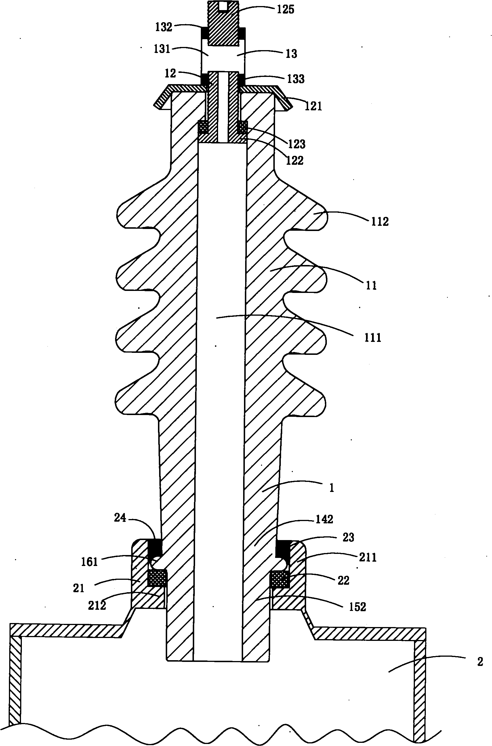
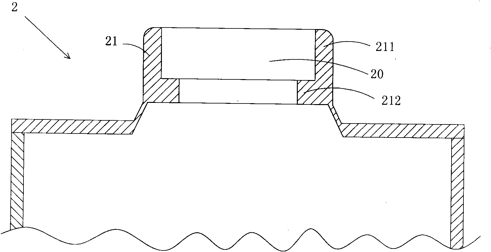
[0023] figure 1 and figure 2 A first embodiment of the invention is shown in which, figure 1 It is a structural schematic diagram of the first structure of the present invention; figure 2 for figure 1 A schematic diagram of the structure of the capacitor case in the power capacitor shown.

[0024] This embodiment is a power capacitor, see figure 1 and figure 2 , this kind of power capacitor includes a capacitor housing 2 and a terminal 1 fixed on the capacitor housing, and the terminal 1 includes a ceramic insulator body 11 and a wiring assembly 12 arranged on the top of the ceramic insulator body 11; the ceramic The insulator body 11 is provided with a through hole 111 along its central axis, a plurality of sheds 112 are provided on the middle outer wall of the insulator body, and a welding part 113 is provided at the lower part of the insulator body; The fixed installation base 20 of the ceramic insulator body 11 is fixedly installed; the welding part 113 of the ins...

Embodiment 2

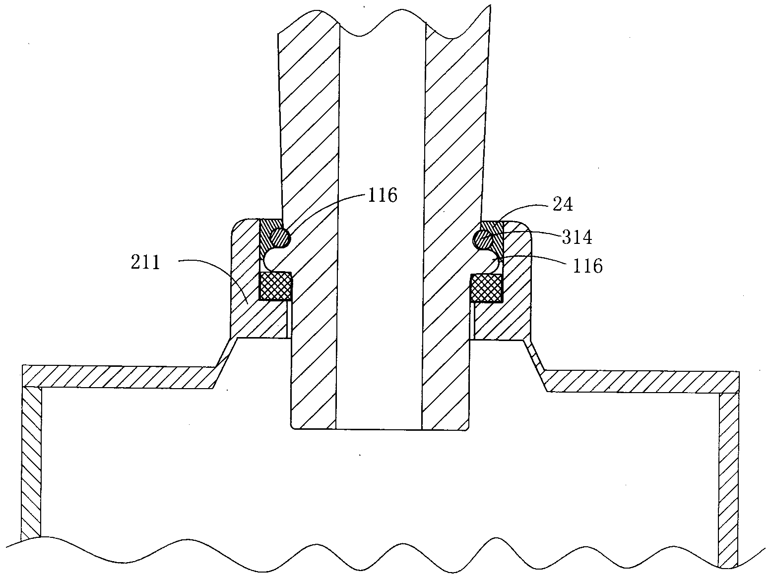
[0030] image 3 It is a structural schematic diagram of the second structure of the present invention, showing the second specific implementation manner of the present invention.

[0031] This embodiment is basically the same as Embodiment 1, the difference is: see image 3 , there is also an annular groove 116 between the annular positioning boss 161 and the umbrella skirt 112, the top of the sleeve area 211 of the fixed installation seat 20 is higher than the annular groove 116, the annular A metal retaining ring 314 is disposed in the groove 116 ; the metal retaining ring 314 is fixedly connected to the inner wall of the casing area 211 of the fixed installation seat 20 by soldering 24 .

Embodiment 3

[0033] Figure 4 and Figure 5 A third embodiment of the invention is shown, in which Figure 4 It is a structural schematic diagram of the third structure of the present invention; Figure 5 for Figure 4 A schematic diagram of the structure of the capacitor case in the power capacitor shown.

[0034] This embodiment is basically the same as Embodiment 1, the difference is: see Figure 4 and Figure 5 The welding portion 113 of the insulator body includes a blocking surface 141 with a larger outer diameter and a welding pipe 142 with a smaller outer diameter located below the blocking surface 141, the basic shape of the welding portion 113 is T-shaped; The fixed mounting base 20 includes a mounting tube 21 with a linear cavity, the mounting tube 21 is sheathed on the outer wall of the welding tube 142 in the welding part 113 of the insulator body, and the top end of the mounting tube 21 is located in the welding part 113 Below the blocking surface 141 ; the fixed mounti...


PUM


Abstract

The invention discloses a power capacitor which comprises a capacitor shell and a wiring terminal fixed on the capacitor shell. The wiring terminal comprises a ceramic insulator main body and a wiring assembly arranged on the top end of the ceramic insulator main body. The ceramic insulator main body is provided with a through hole along the central axis per se, the external wall of the middle part of the insulator main body is provided with a plurality of umbrella skirts, and the lower part of the insulator main body is provided with a welding part. The capacitor shell is provided with a fixed installation seat for fixedly installing the ceramic insulator main body. The welding part of the insulator main body is fixed on the fixed installation seat through a welding mode. The invention has the advantages of fewer processing steps and lower manufacturing cost.

Description

technical field [0001] The invention relates to the technical field of structural design of high-voltage power capacitors, in particular to a power capacitor. Background technique [0002] Existing high-voltage power capacitors include a capacitor shell and ceramic insulator devices arranged on the capacitor shell; each ceramic insulator device includes a ceramic insulator body, a wiring assembly welded on the top of the insulator, and a fixed mounting seat welded and fixed on the lower part of the insulator . When manufacturing and assembling this kind of ceramic insulator device, it is necessary to fix the fixed mounting seat made of metal on the outer wall of the insulator body by welding; when installing this kind of ceramic insulator device, it is first necessary to stamp out A tubular mounting interface that matches the shape of the fixed mounting seat, and then insert the ceramic insulator with the fixed mounting seat into the mounting interface, and weld the fixed m...

Claims


Application Information

Patent Timeline
IPC IPC(8): H01G4/228H01G4/224
Inventor 王海龙
Owner 王海龙
Why Eureka
Try Eureka