Dead-zone compensation method for voltage source inverter

A voltage source inverter and dead-time compensation technology, applied in the direction of controlling electromechanical brakes, electrical components, controlling generators, etc., can solve the current vector angle estimation lag, high isolation requirements for voltage sampling circuits, and difficulty in ensuring current vector angle estimation. Accuracy and other issues

Inactive Publication Date: 2010-12-15
INST OF ELECTRICAL ENG CHINESE ACAD OF SCI
View PDF4 Cites 30 Cited by
  • Summary
  • Abstract
  • Description
  • Claims
  • Application Information

AI Technical Summary

Problems solved by technology

At low frequency, due to PWM noise, zero current clamping phenomenon, speed of current crossing zero point, and wandering during crossing, etc., it is very difficult to accurately detect current crossing zero point
[0003] The patent "Dead Zone Compensation Method of Inverter" with the application number of 00122378 calculates the two-axis current in the rotating coordinate system oriented by the space voltage vector, calculates the vector angle of the synthesized current vector after low-pass filtering, and then determines the three Phase-to-phase current polarity, but due to the use of low-pass filters, this method will cause the problem of lagging current vector angle estimation. At the same time, it is difficult to ensure the accuracy of current vector angle estimation at low frequencies, and this method is more complicated and takes up a lot of CPU resources.
Patent Application No. 200610144322 "A Dead Zone Compensation Method for Space Vector Pulse Width Modulation Output" compensates the PWM pulse wi

Method used


Image

  • Dead-zone compensation method for voltage source inverter
  • Dead-zone compensation method for voltage source inverter
  • Dead-zone compensation method for voltage source inverter

Examples


Embodiment Construction

[0026] The present invention will be further described below in conjunction with the accompanying drawings and specific embodiments.

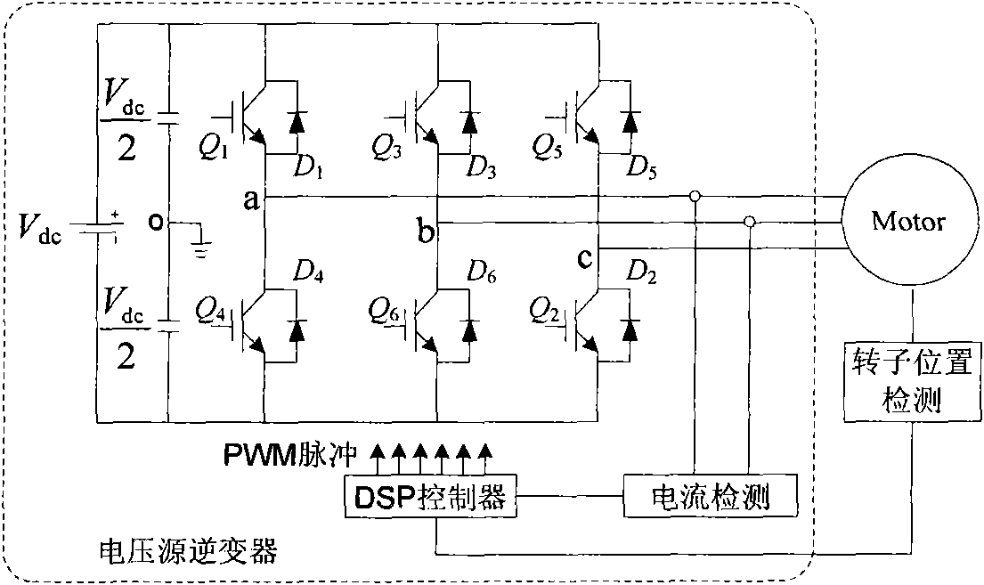
[0027] Taking the permanent magnet synchronous motor vector control system powered by a voltage source inverter as an example, the dead zone compensation method of the present invention is described, figure 1 Is the schematic diagram of the system structure. Such as figure 1 As shown, the voltage source inverter is composed of power modules, current sensors, and DSP controllers. figure 1 The power module of the medium voltage source inverter is Infineon FF600R06ME3; the parameters of the permanent magnet synchronous motor: the rated power is 20kW, the rated speed is 2500rpm, the number of pole pairs is 3, the stator phase resistance is 26mΩ, and the d-axis inductance is 0.52mH. The q-axis inductance is 1.02mH, and the permanent magnet flux linkage is 0.129Wb. The rotor position detection device installed on the motor detects the position of ...


PUM


Abstract

The invention relates to a dead-zone compensation method for a voltage source inverter. The method comprises the following steps of: performing dead-time compensation according to the acting time t1 and t2 of two non-zero base voltage vectors in a pulse-width modulation (PWM) period Ts and the practical dead time Td of the voltage source inverter based on the conventional space vector pulse width modulation (SVPWM) modulation strategy; adding two dead-time compensation time tcom1 and tcom2 and the acting time t1 and t2 of the two non-zero base voltage vectors to obtain new acting time t11 and t22 of the two non-zero base voltage vectors in the PWM period; and operating the new acting time t11 and t22 of the two non-zero base voltage vectors by using the SVPWM modulation strategy to generate a needed PWM pulse and finally realize deal-time compensation and zero-current clamping effect inhibition.

Description

technical field [0001] The invention relates to a dead zone compensation method of a voltage source inverter. Background technique [0002] The turn-on signals of the upper and lower tubes of the same bridge arm of the three-phase voltage source inverter (VSI) are complementary. In order to prevent shoot-through, a period of dead time must be artificially inserted during the switching action of the power tubes. Its cumulative effect leads to motor phase voltage and phase current distortion, zero current clamping effect, and torque and speed ripple, degrading system performance Error|No reference source found. . Therefore, in order to improve the system performance, it is very necessary to study the dead zone of the voltage source inverter (VSI). Accurate dead zone compensation generally requires two conditions: the error voltage ΔV and the correct estimation of the current direction. The calculation of the error voltage is based on the average error theory. The average di...

Claims


Application Information

Patent Timeline
IPC IPC(8): H02P21/14H02P27/08
Inventor 周华伟温旭辉赵峰张剑郭新华
Owner INST OF ELECTRICAL ENG CHINESE ACAD OF SCI
Why Eureka
Try Eureka