Ultrasonic transmitting/receiving device

An ultrasonic and receiver technology, applied in the field of ultrasonic sending and receiving, can solve the problems of ultrasonic sending and receiving barriers, inability to discharge water, etc.

Inactive Publication Date: 2010-12-15
OVAL CORP
View PDF4 Cites 0 Cited by
  • Summary
  • Abstract
  • Description
  • Claims
  • Application Information

AI Technical Summary

Problems solved by technology

That is, when, for example, condensation occurs inside the inner side case 8, water cannot be discharged due to the presence of the sealing member 17, and as a result, there is a problem of hindering the transmission and reception of ultrasonic waves.

Method used


Image

  • Ultrasonic transmitting/receiving device
  • Ultrasonic transmitting/receiving device
  • Ultrasonic transmitting/receiving device

Examples


Embodiment Construction

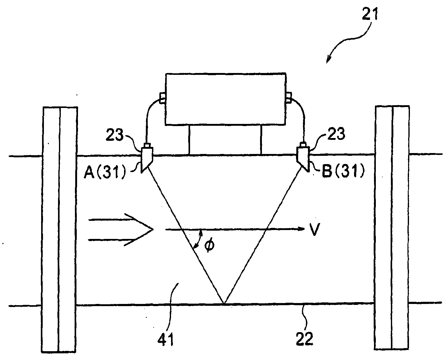
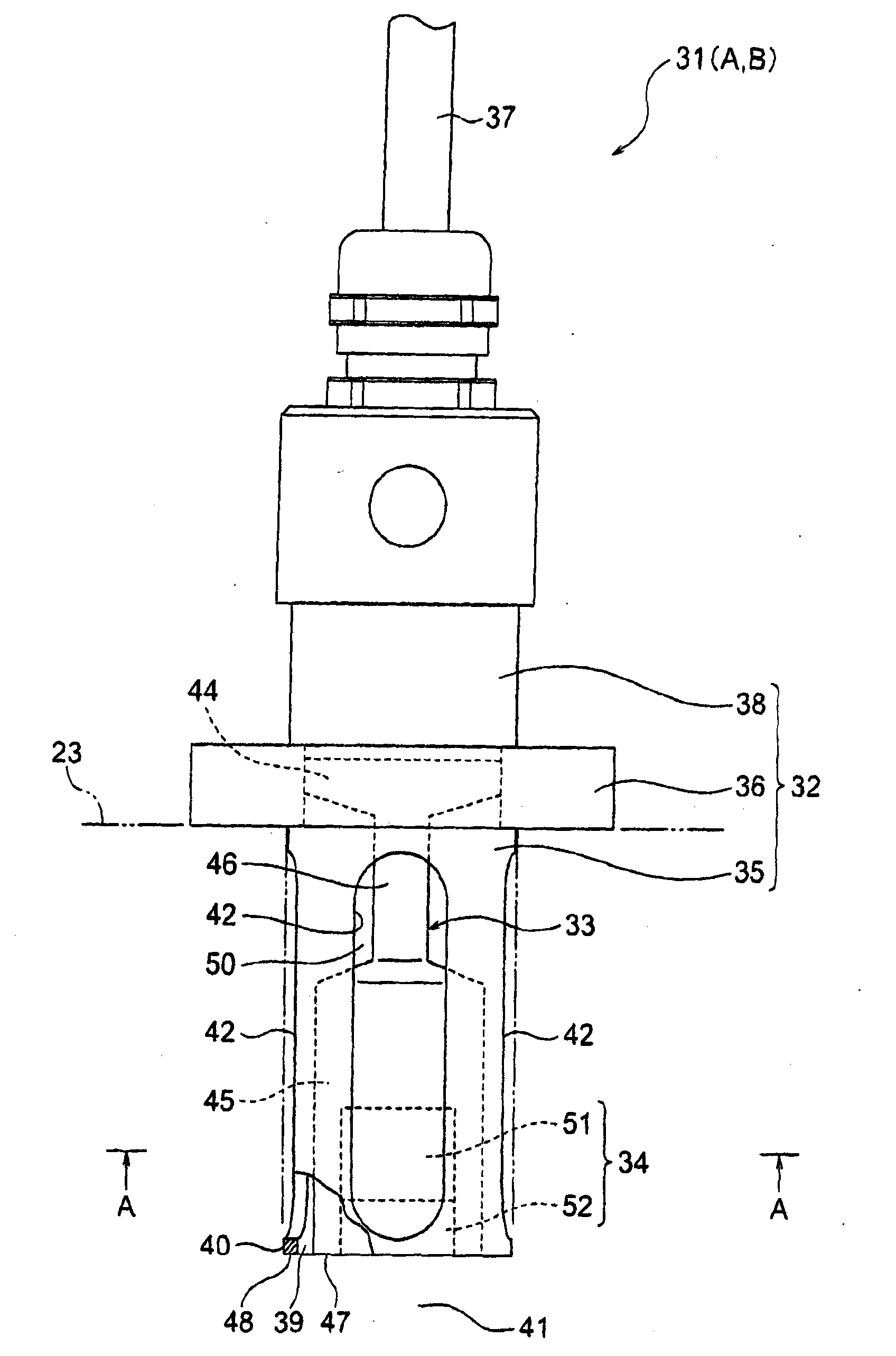
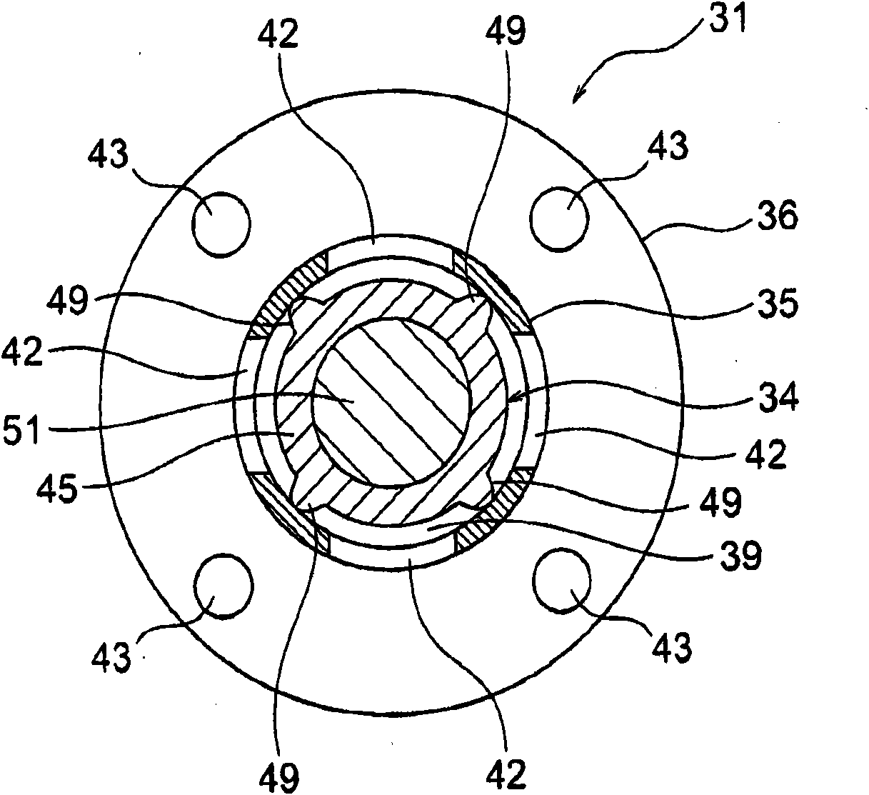
[0025] Below, while referring to the attached Figure 1 side to explain. figure 1 It is a figure which schematically shows the measurement principle of an ultrasonic flowmeter. also, figure 2 It is a front view showing an embodiment of the ultrasonic transmitter-receiver of the present invention, image 3 yes figure 2 The A-A line sectional view, Figure 4 It is a perspective view of an ultrasonic transmitter and receiver.

[0026] exist figure 1 Among them, the ultrasonic flowmeter 21 is used for gas measurement, and includes a measurement tube 22 through which a fluid to be measured (for example, gas) flows at a flow velocity V. The measurement tube 22 is provided with ultrasonic transmitters A and B via support tubes 22 and 23 . The ultrasonic flowmeter 21 is configured to obtain a flow rate based on a difference in propagation time of ultrasonic waves alternately transmitted and received between the ultrasonic transmitters A and B. Ultrasonic flowmeter 21 adopt...


PUM


Abstract

A gap (39) is so formed that, even if dew condensation occurs therein, the water content is released therethrough by the weight of the dew condensation and by a negative pressure applied thereto from a fluid to be measured which flows through a measurement pipe. The gap (39) communicates with a transmitting/receiving space (41) for transmitting/receiving an ultrasonic. A plurality of projections are disposed on the outer surface of the other end part (45) at equal pitches to keep the state of the gap (39). A plurality of housing through-holes (42) are so formed inside a housing (35) as to extend through the inner surface and the outer surface thereof.

Description

technical field [0001] The present invention relates to an ultrasonic transmitter-receiver, and more particularly, to an ultrasonic transmitter-receiver used in an ultrasonic flowmeter for gas. Background technique [0002] For example, the following technology is disclosed in Japanese Patent No. 3639570. exist Figure 8 In (a), the ultrasonic flowmeter 1 includes a measuring tube 2 through which a fluid to be measured flows at a flow velocity F. FIG. The measuring tube 2 is provided with support tubes 3 and 4 facing each other at an angle β with respect to the tube axis O-O. The ultrasonic transmitter-receiver 5 is coaxially fixed on the support tube 3 and the ultrasonic transmitter-receiver 6 is in a facing state in the support tube 4 . [0003] The ultrasonic flowmeter 1 transmits ultrasonic waves from the ultrasonic transmitter-receiver 6 in a positive direction with respect to the airflow for a predetermined period of time as indicated by an arrow Ua, and receives the...

Claims


Application Information

Patent Timeline
Patent Type & Authority Applications(China)
IPC IPC(8): H04R1/02G01F1/66H04R17/00
CPCG01F1/663G01F1/662G01F15/14H04R1/02H04R17/00
Inventor 中泽博昭
Owner OVAL CORP
Why Eureka
Try Eureka