Assembled buckle structure

A buckle structure, combined assembly technology, applied in the direction of transportation, packaging, vehicle parts, etc., can solve the problems of poor deformation ability of elastic clips, falling off of decorative strips, insufficient deformation and other problems

Inactive Publication Date: 2010-12-22
NINGBO XINTAI MACHINERY
View PDF5 Cites 9 Cited by
  • Summary
  • Abstract
  • Description
  • Claims
  • Application Information

AI Technical Summary

Problems solved by technology

[0004] 1. During assembly, if the buckle requires too much insertion force, it will take time and effort for the operator to assemble; if the deformation of the buckle is insufficient, if the buckle is inserted forcibly, the buckle will break
[0005] 2. After assembly, if the insertion force required by the buckle is small, the gap between the decorative strip and the counterpart will be too large or uneven, and the buckle will easily loosen or fall off relative to the counterpart, and even the decorative strip will fall off
The deformability of the elastic clips in the aforementioned patents is relatively poor, so the design of the insertion force of this type of clip cannot meet the requirements very well, and generally requires a relatively large insertion force
[0007] Now take the fixing method of installing the door frame trim to the door frame as an example. The outer end of the door frame trim is provided with an end cover. A part of the body of the decorative strip needs to be punched out, so that the product can be easily turned over here, so it is necessary to design a buckle structure on the end cover to fix the product on the inner panel of the door, which is required to be easy to insert and not easy to pull out; at the same time After the surface of the end cover is chrome-plated, the material will become brittle and easy to break, which will affect the buckle assembly on the end cover. Therefore, a buckle structure must be designed to avoid the impact caused by the brittle chrome plating of the end cover. Easy to insert and not easy to pull out

Method used


Image

  • Assembled buckle structure
  • Assembled buckle structure
  • Assembled buckle structure

Examples


Embodiment Construction

[0032] The present invention will be further described in detail below in conjunction with the accompanying drawings and embodiments.

[0033] like Figure 1-13 Shown is an embodiment of the present invention.

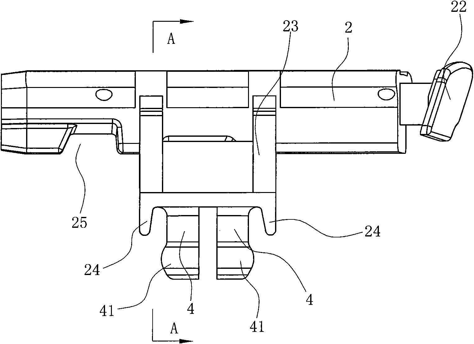
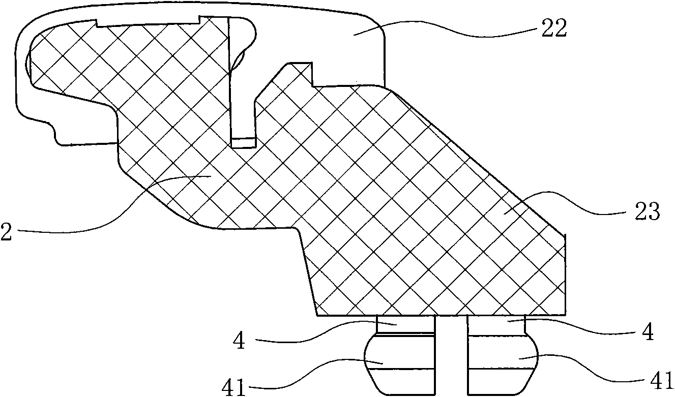
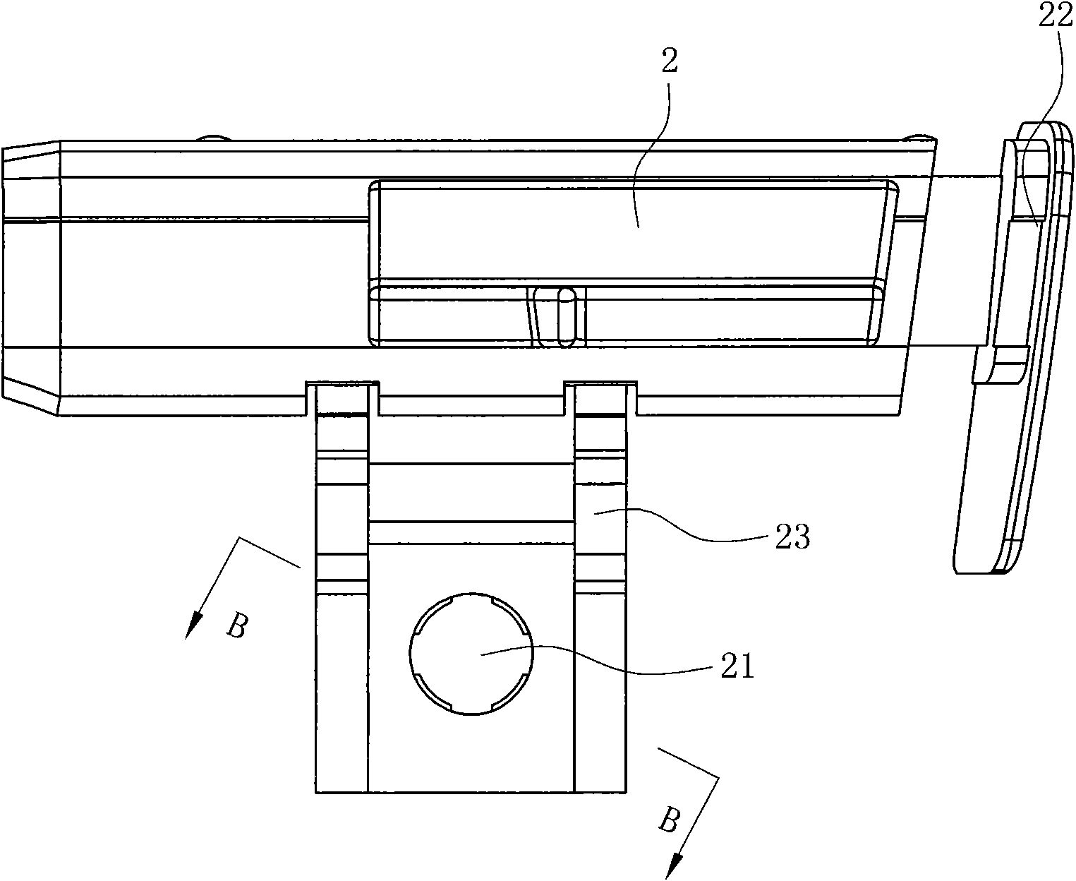
[0034] A buckle structure adopting combined assembly, the buckle structure is a buckle for installing a door frame trim strip on a door frame.

[0035] like Figure 1~5 As shown, it includes a base 2 for inserting into the decorative strip 1 (door frame trim) for the positioning of the decorative strip 1. The base 2 has a decorative surface 22 that can cover the outer end surface of the decorative strip 1. The surface of the decorative surface 22 is Chrome plating is performed to match the color of the decorative strip, and the front of the base body 2 has a bayonet 25 for auxiliary fixing of the decorative strip 1 . The side portion of the base body 2 has a connecting portion 23 extending forward, and the lower end surface of the connecting portion 23 has a protrud...


PUM


Abstract

The invention relates to an assembled buckle structure which comprises a substrate (2) to be inserted in a decorative strip (1). The lower end surface of the substrate (2) is provided with a clamping part which is clamped in a mounting hole (31) of a counterpart piece (3). The assembled buckle structure is characterized in that the clamping part comprises a plurality of elastic strips (4) which extend downwards and are arranged at intervals, the elastic strips are encircled into a loop matched with the shape of the mounting hole on the counterpart piece, and the lower part at the outer side of each elastic strip is provided with clamping pins (41) which protrude outwards and gradually expand from bottom to top; and a bolt (5) is inserted from bottom to top in the space encircled by the elastic strips, and the peripheral surface of the bolt acts on the inner end surfaces of the elastic strips so that the elastic strips keep the outwards bracing trend. Because of the favorable elasticity of the elastic strips, the interference between the clamping pin size and the mounting hole is smaller, the elastic strips can be inserted in the mounting hole by only needing small inserting force, and the peripheral surface of the bolt can brace the elastic strips outwards so that the elastic strips are clamped in the mounting hole and hardly drawn out.

Description

technical field [0001] The invention relates to a vehicle accessory, in particular to a snap-fit ​​structure for installing a decorative strip on an automobile. Background technique [0002] The tailgate of the car, the cover of the luggage compartment or the corresponding position of the car door frame are generally equipped with decorative strips to play a decorative role on the car. In order to install the decorative strips to the corresponding positions of the car conveniently and reliably, the decorative strips must pass through Glue, double-sided tape, plastic or metal buckles, screws and other connection structures are installed on the car. Among these connection structures, plastic buckle connection is the most common and convenient, but the design is the most difficult. During assembly, the clips are first installed on the decorative bright strips through the assembly process, and then the decorative strips and clips are assembled to the corresponding positions of ...

Claims


Application Information

Patent Timeline
Patent Type & Authority Applications(China)
IPC IPC(8): B60R13/04
Inventor 卢孝贵
Owner NINGBO XINTAI MACHINERY
Why Eureka
Try Eureka