
Cylinder type electronic needle selecting device

An electronic needle selection and cylinder type technology, which is applied in knitting, weft knitting, textiles and papermaking, etc., to achieve the effect of improving adaptability, increasing production capacity and quick replacement

Inactive Publication Date: 2010-12-22
ZHEJIANG SCI-TECH UNIV
View PDF5 Cites 2 Cited by
  • Summary
  • Abstract
  • Description
  • Claims
  • Application Information

AI Technical Summary

Problems solved by technology

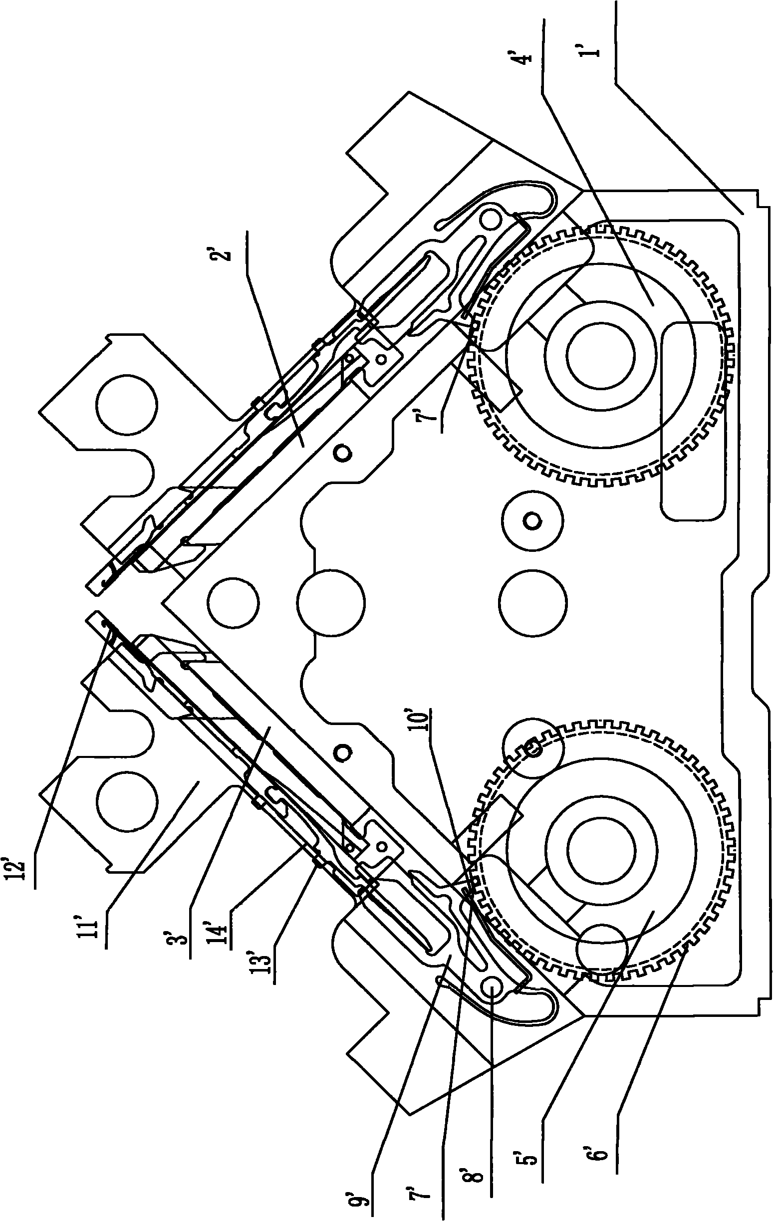
When the bird piece protrusion 10' is located in the roller groove 6' without the roller pin 7', due to the reset action of the spring on the bird piece 9', the bird piece 9' rotates clockwise along the bird piece shaft 8', causing the bird The convex head 10' is close to the inner concave surface of the roller groove 6'. At this time, the needle butt 13' moves down and is located in the needle bed groove 14', and the triangular action of the machine head cannot be made, so the needle is not selected.
[0006] This mechanical needle drum selection method mainly has the following problems. 1. Gloves of various specifications need to be realized in different arrangements, so each replacement The equipment (roller, bird sheet, etc.) must be disassembled and assembled for each variety and size. Generally, it takes 4 hours to replace it once, which is time-consuming and labor-intensive. Moreover, frequent disassembly and assembly of the needle drum will easily damage the mechanism itself and the needle drum.
(The needle drum itself is easy to break after being disassembled several times)
2. Due to structural reasons, the number of horizontal grooves in the needle drum is limited, and it is impossible to produce gloves such as jacquard and complex varieties
3. In actual production, when the machine has been used for a certain period of time, due to mechanical wear and other reasons, it is very easy to have chaotic needle drums, which affects the quality of the product

Method used


Image

  • Cylinder type electronic needle selecting device
  • Cylinder type electronic needle selecting device
  • Cylinder type electronic needle selecting device

Examples


Embodiment Construction

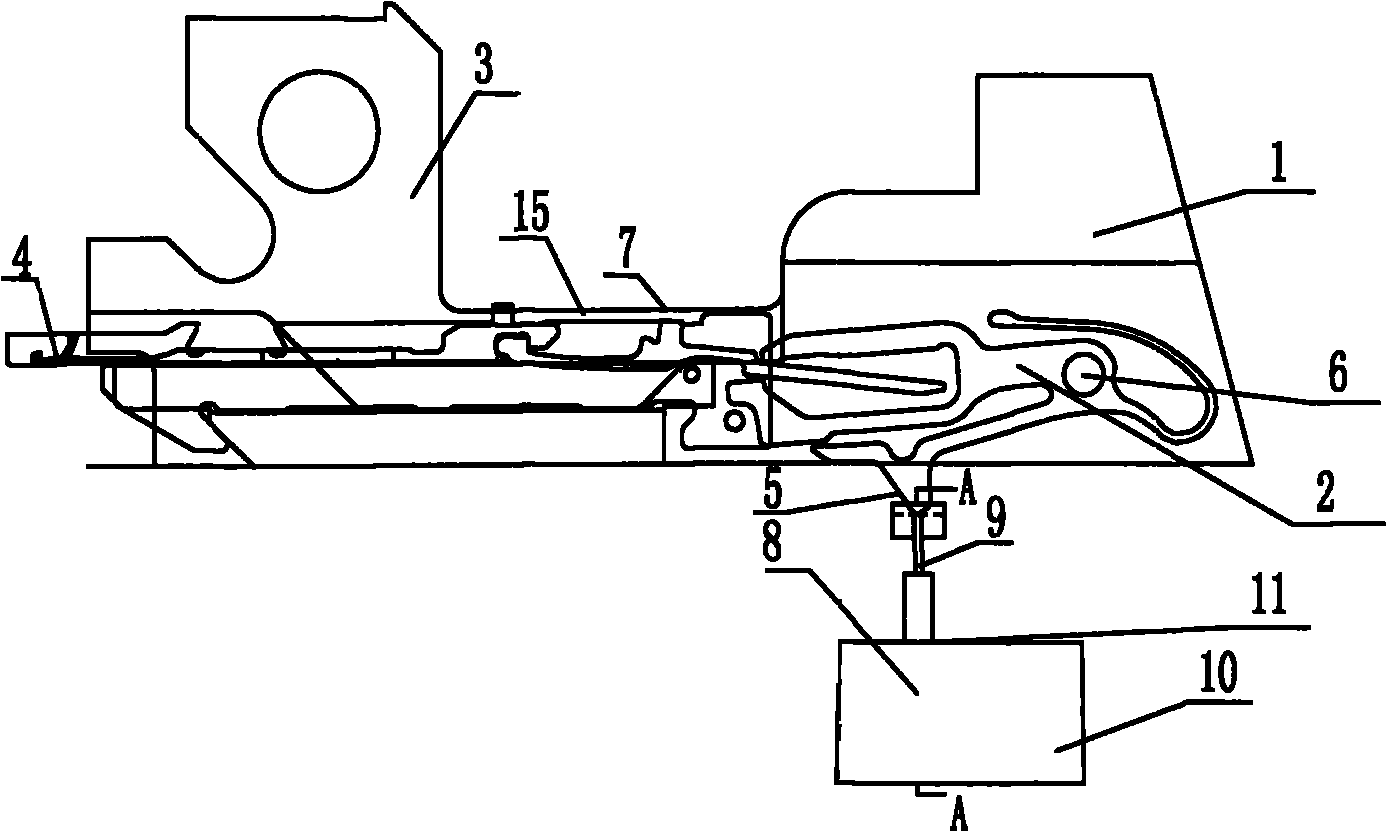
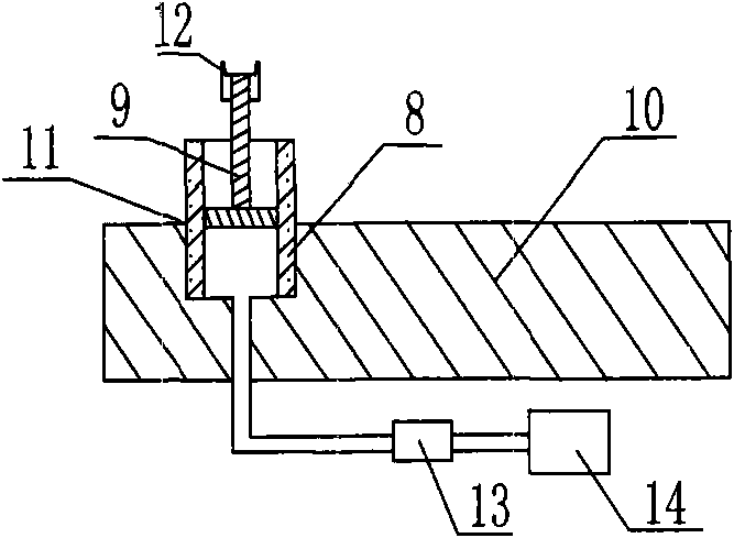
[0019] The electronic needle selection device of a cylinder type glove machine referred to in the present invention includes a needle plate 1 installed on a frame, on which a bird piece 2, a machine head 3, and knitting needles 4 are installed. The bird piece 2 includes the bird piece protrusion 5, the bird piece shaft 6, and the needle butt 7, wherein the bird piece 2 is fixedly connected with the needle plate 1 through the bird piece shaft 6, and the cylinder type needle selection device is installed on the frame below the needle plate 1, The cylinder type needle selection device includes a cylinder 8, a piston 9, and a cylinder frame 10, wherein the cylinder frame 10 is installed on the frame below the needle plate 1, and the cylinder frame 10 is provided with a hole 11, and the hole 11 is fitted with a Cylinder 8, piston 9 is installed in the cavity of cylinder 8, and the head of piston 9 is provided with groove 12, and the depth of groove 12 matches with the thickness of b...


PUM


Abstract

The invention discloses a cylinder type electronic needle selecting device which comprises a needle plate mounted on a rack, a pawl, a nose and a knitting needle are mounted on the needle plate, the pawl comprises a pawl convex head, a pawl shaft and a butt, wherein the pawl is fixedly connected with the needle plate through the pawl shaft, a cylinder type needle selecting device is mounted on the rack positioned below the needle plate, the cylinder needle selecting device comprises a cylinder, a piston and a cylinder frame, wherein the cylinder frame is mounted on the rack below the needle plate, a hole is formed on the cylinder frame, the cylinder is clamped and mounted in the hole, the piston is mounted in a cavity body of the cylinder, a groove is formed at the head part of the piston, and the depth of the groove is matched with the thickness of the pawl convex head. The device can realize the rapid replacement of product varieties and improve the adaptability of the varieties; as the cylinder type needle selecting way is adopted, the needle selection and the change are not limited by the number of transverse grooves of a mechanical needle drum, thereby raising the needle-selecting speed and further increasing the production capacity.

Description

technical field [0001] The invention relates to a cylinder type electronic needle selection device. Background technique [0002] With the improvement of people's labor safety awareness and the need to pursue fashion, the types and demands of gloves are increasing day by day. The glove knitting machine has also transitioned from the manual control type to the computer automatic control type, and at the same time, the number and functions of the glove knitting machine are constantly increasing. The types of woven gloves generally include labor protection gloves, various magic fashion gloves, half-finger gloves, full-finger gloves, cold-proof gloves and fashion gloves, etc. The specifications are large, medium and small. Since the computerized automatic glove machine can be used not only in household production, but also in large-scale enterprise production, the domestic demand is relatively large. [0003] Domestic glove machine manufacturers started in 2003. The needle se...

Claims


Application Information

Patent Timeline
Patent Type & Authority Applications(China)
IPC IPC(8): D04B15/32D04B15/66
Inventor 袁嫣红张建义魏俊民
Owner ZHEJIANG SCI-TECH UNIV
Learn More