Automatic hydrant

A technology of automatic water supply and water supply cock, which is applied in the direction of engine components, valve details, diaphragm valves, etc., can solve the problems of high production cost and difficult to guarantee sealing performance

Inactive Publication Date: 2010-12-22
山东江河科技咨询中心
View PDF10 Cites 3 Cited by
  • Summary
  • Abstract
  • Description
  • Claims
  • Application Information

AI Technical Summary

Problems solved by technology

In addition, when the control ball moves down and the water is cut off, it is difficult to gua...

Method used


Image

  • Automatic hydrant
  • Automatic hydrant
  • Automatic hydrant

Examples


Embodiment Construction

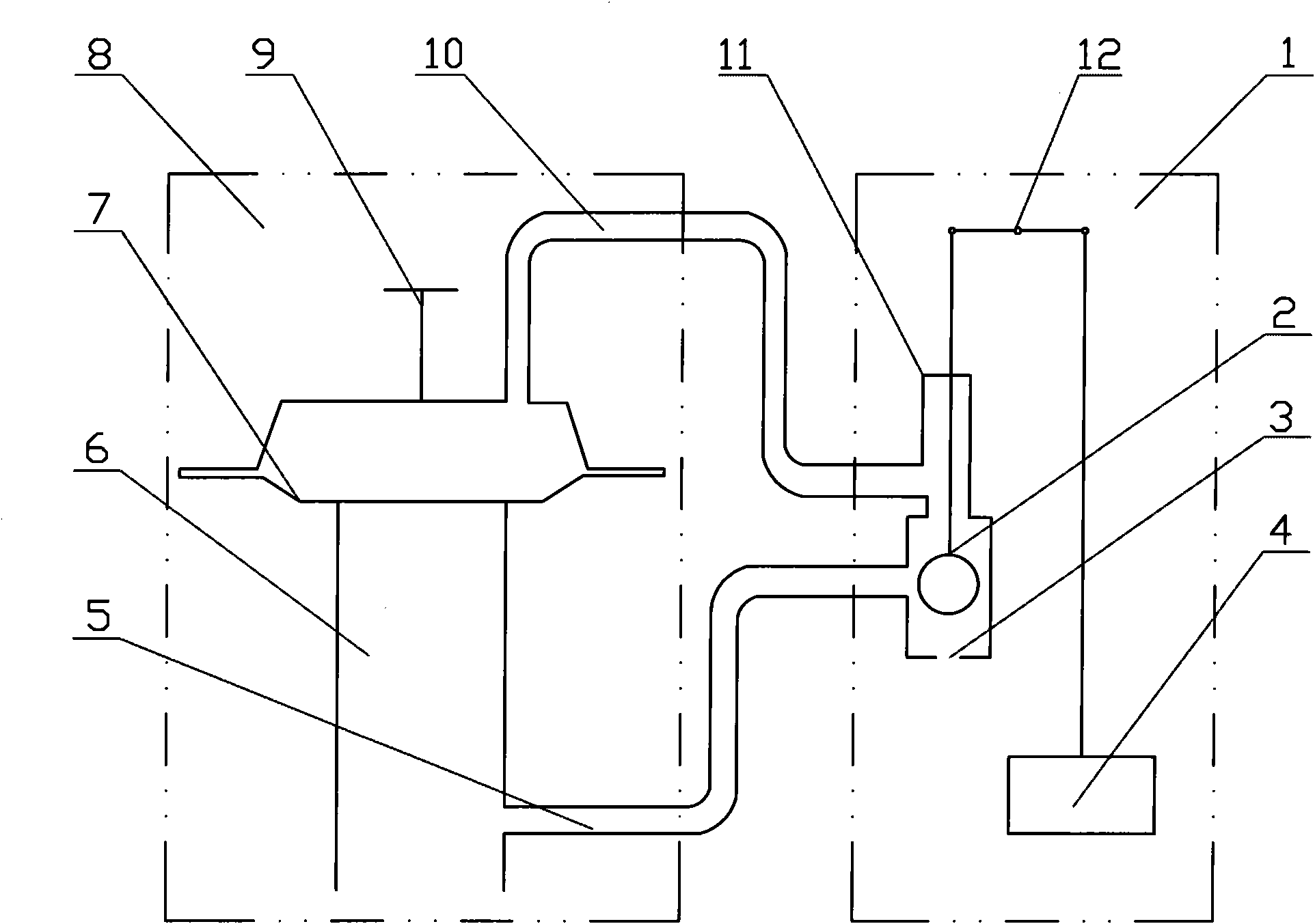
[0028] Refer to the attached Figure 4 , which shows an automatic water supply cock, including a water supply cock body 9 and a sensor 1 for controlling the state of the water supply cock body, wherein the water supply cock body includes a water outlet pipe 6 for connecting to water supply equipment and is blocked by a given pressure contact The diaphragm 8 of the outlet pipe nozzle and the diaphragm chamber formed on the upper side of the diaphragm; the sensor includes a float mechanism 5 and a switching device 12 controlled by the float mechanism, and the switching device has a second diaphragm connected to the diaphragm chamber. A water control pipe 11 and a second water control pipe 6 connected to the water outlet pipe, the switching device includes a valve core 17 with a degree of freedom of up and down movement controlled by the float mechanism and a pressure relief port arranged on the switching device 16. The switching device is in the communication state between the f...


PUM


Abstract

The invention discloses an automatic hydrant, comprising a hydrant body and a sensor controlling the state of the hydrant body, wherein, the hydrant body comprises a water outlet pipe, a diaphragm and a diaphragm chamber, wherein, the water outlet pipe is used for being connected with water supply equipment; the diaphragm is contacted with the opening plugged on the water outlet pipe through the given pressure; and the diaphragm chamber is formed on the upper side of the diaphragm; the sensor side comprises a floater mechanism and a switching device controlled by the floater mechanism; the switching device comprises a first water control pipe connected with the diaphragm chamber and a second water control pipe connected with the water outlet pipe; the switching device comprises a valve plug and a pressure release opening, wherein, the valve plug is controlled by the floater mechanism and has the freedom degree of the up-and-down movement; and the pressure release opening is arranged on the switching device; the switching device is in a communicated state of the first water control pipe and the pressure release opening at the dead point position of the valve plug; the other dead point position is in a communicated state of the first water control pipe and the second water control pipe. The automatic hydrant has compact structure, low cost and good water control effect.

Description

technical field [0001] The invention relates to an automatic water supply cock, comprising a water supply cock body and a sensor for controlling the state of the water supply cock body, wherein the water supply cock body includes a water outlet pipe for connecting water supply equipment and is blocked at the mouth of the water outlet pipe by a given pressure contact The diaphragm and the diaphragm chamber formed on the upper side of the diaphragm; the sensor includes a float mechanism and a switching device controlled by the float mechanism, the switching device has a first water control pipe connected to the diaphragm chamber and connected to the The second water control pipe of the water outlet pipe. Background technique [0002] Flood irrigation of paddy field crops such as rice is a relatively common irrigation method, and it is necessary to keep the depth of the water layer within a predetermined range during a specific growth stage of the crops. The conventional flood...

Claims


Application Information

Patent Timeline
IPC IPC(8): F16K7/14F16K31/24F16K37/00F16K47/02
Inventor 周玉印张士军周海涛沈荣开张瑜芳
Owner 山东江河科技咨询中心
Why Eureka
Try Eureka