
Lens module

A lens module and lens holder technology, applied in the field of optical systems, can solve the problems affecting the optical coupling between optical imaging elements and image sensors, the separation of the lens barrel and the lens holder, and the lack of tight combination of the lens barrel and the lens holder.

Inactive Publication Date: 2010-12-22
HONG FU JIN PRECISION IND (SHENZHEN) CO LTD +1
View PDF0 Cites 8 Cited by
  • Summary
  • Abstract
  • Description
  • Claims
  • Application Information

AI Technical Summary

Problems solved by technology

[0004] Generally speaking, the torque between the lens barrel and the lens base of the lens module is too small, that is, the external thread of the lens barrel and the internal thread of the lens base are too loose, which will easily cause the lens barrel and the lens base to separate from each other; Too much torque means that the outer thread of the lens barrel and the inner thread of the lens base are too tightly matched, which will cause the outer thread of the lens barrel and the inner thread of the lens base to wear each other, only the torque value between the lens barrel and the lens base is within a certain range The lens module is a qualified product
[0005] However, it requires high processing costs to form perfectly matched external threads and internal threads on the small lens barrel and lens holder, respectively.
Moreover, after the assembly of the lens module is completed, a torque test is required to eliminate the lens modules whose torque value between the lens barrel and the lens base is not within the specified range, which will consume a lot of manpower and material resources
In addition, the external thread of the lens barrel and the internal thread of the lens base will wear due to the interaction during the repeated assembly or disassembly of the lens module. The optical coupling between the imaging element and the image sensor affects the imaging quality of the lens module

Method used


Image

  • Lens module
  • Lens module
  • Lens module

Examples


Embodiment Construction

[0016] The lens module of the technical solution will be further described in detail below with reference to the accompanying drawings and multiple embodiments.

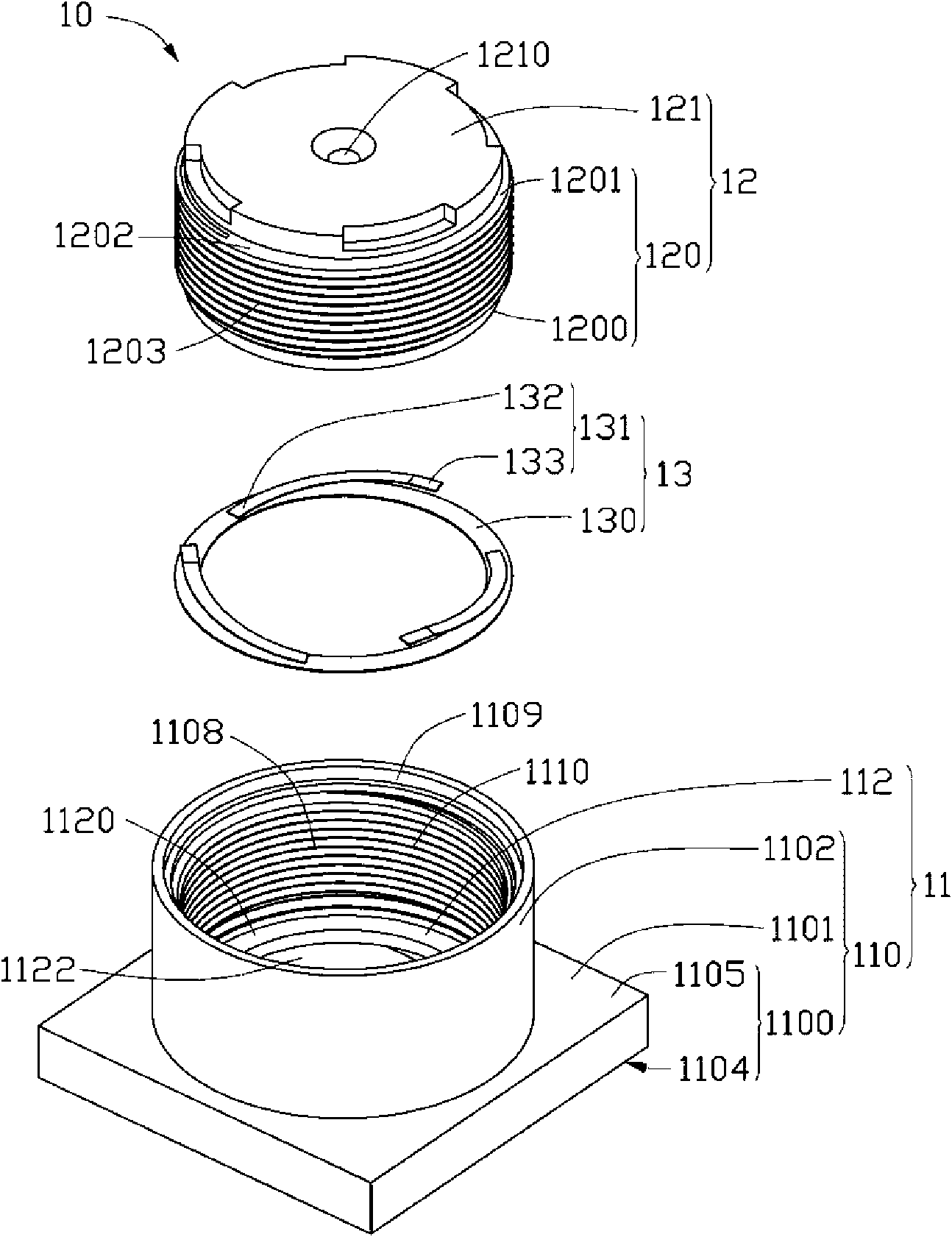
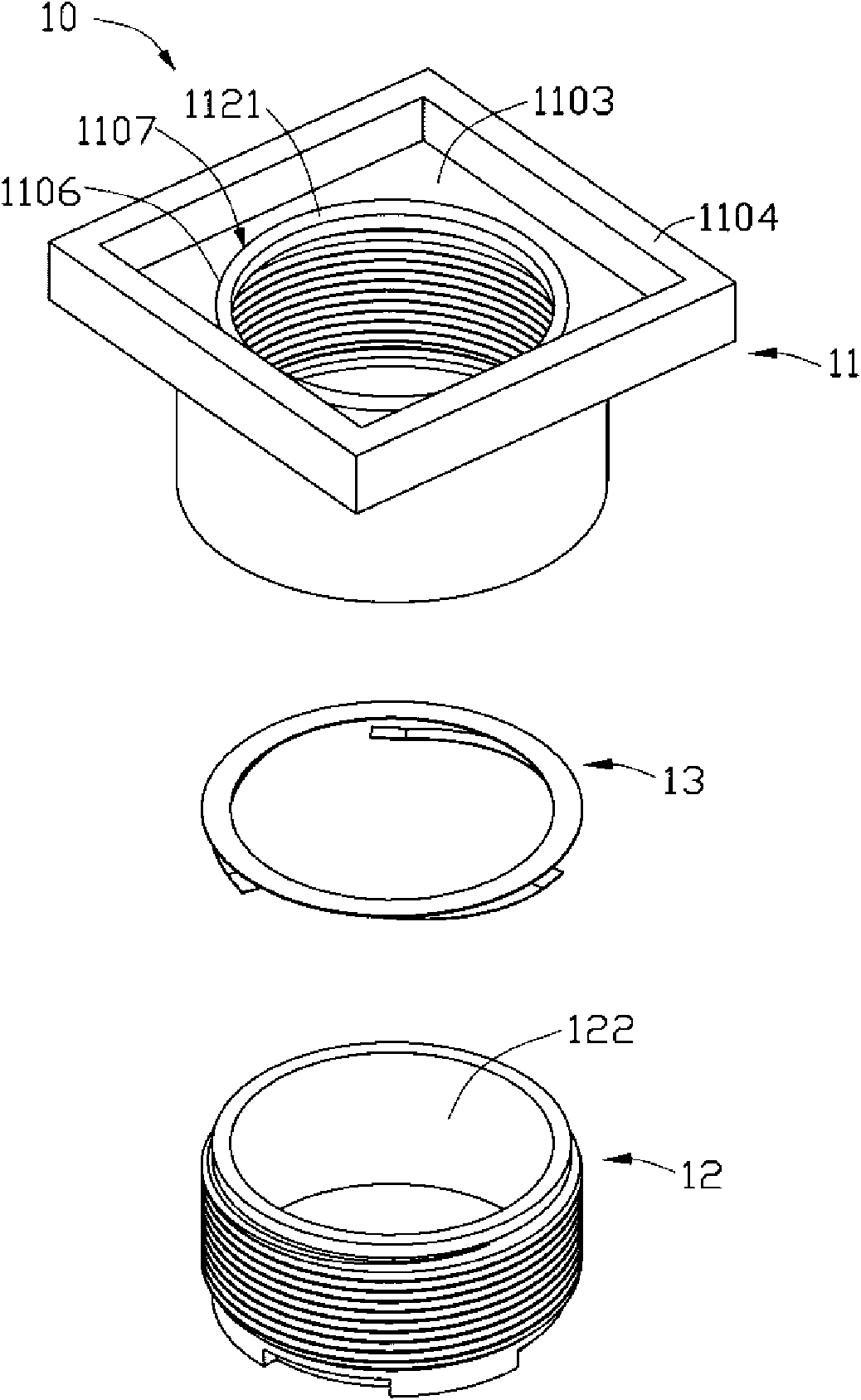
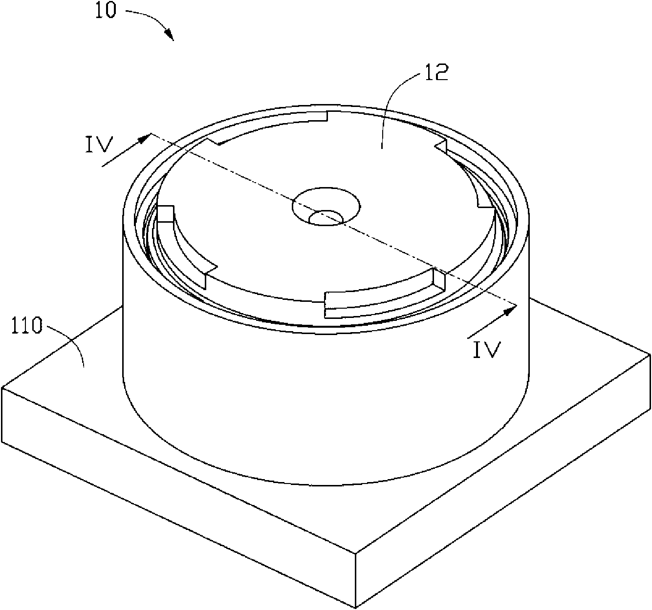
[0017] Please refer to Figure 1 to Figure 5 , A lens module 10 provided by an embodiment of the technical solution includes a lens holder 11, a lens barrel 12, and an elastic element 13.

[0018] The lens holder 11 includes a holder body 110 and a bearing platform 112. The carrier 112 extends from the base 110 to a direction close to the central axis of the lens module 10.

[0019] The base 110 includes a first side wall 1100, a first bottom wall 1101, and a second side wall 1102 that are connected in sequence.

[0020] The first side wall 1100 encloses and forms a first receiving cavity 1103 for receiving the image sensor. The cross section of the first receiving cavity 1103 may be square. The first side wall 1100 has a first end surface 1104 and a second end surface 1105 opposite to each other.

[0021] The first bottom...


PUM


Abstract

The invention provides a lens module which comprises a lens seat, a lens cone and an elastic element, wherein, the lens seat is provided with a first thread; the lens cone is contained in the lens seat and provided with a second thread which is in loose fit with the first thread of the lens seat; and the elastic element is arranged between the lens seat and the lens cone and used for providing anelastic force along the direction parallel to a central axis of the lens module so that the first thread is contacted with the second thread to fix the lens seat and the lens cone.

Description

Technical field [0001] The invention relates to the field of optical systems, in particular to a lens module with easy control of the torque between the lens barrel and lens holder. Background technique [0002] With the rapid development of multimedia technology, digital cameras, camcorders and mobile phones with cameras are becoming more and more popular among consumers. While people put forward higher requirements on the image quality of objects captured by digital cameras, camcorders and mobile phone cameras, The demand for products such as digital cameras, video cameras and mobile phones with cameras is also increasing. In photographic devices such as digital cameras, video cameras, and mobile phone cameras, the lens module is an indispensable component. [0003] The lens module usually includes a lens barrel, a lens holder, an optical imaging element, and an image sensor. The optical imaging element is contained in the lens barrel, and the image sensor is arranged in the le...

Claims


Application Information

Patent Timeline
IPC IPC(8): G02B7/02H04N5/225G03B30/00
Inventor 李家玮林后尧张嘉淳余盛荣
Owner HONG FU JIN PRECISION IND (SHENZHEN) CO LTD
Learn More