Device and method for measuring beam spot performance of electron gun

A technology of measuring device and measuring method, which is applied in the directions of measuring device, radiation measurement, X/γ/cosmic radiation measurement, etc., can solve the difficulty of quantitatively calculating beam spot size and analyzing uniformity, and cannot verify the use requirements of charge-controlled electron guns , the influence of uncertainty in measurement accuracy, etc., to achieve the effect of simple composition, elimination of charge accumulation, and easy operation

Active Publication Date: 2020-06-19
INST OF ELECTRICAL ENG CHINESE ACAD OF SCI
View PDF5 Cites 5 Cited by
  • Summary
  • Abstract
  • Description
  • Claims
  • Application Information

AI Technical Summary

Problems solved by technology

The direct bombardment method is a qualitative method, and its measurement accuracy is relatively poor
The CCD observation method has certain difficulties in quantitatively calculating the size of the beam spot and analyzing the uniformity
During the use of the occlusion scanning method, due to the interaction between the electron beam and the solid, the interference signal mainly composed of secondary electrons will be generated, which will bring uncertainty to the accuracy of the measurement.
Existing testing methods lack accurate and effective test methods for the beam spot performance test of the charge-controlled electron gun, and cannot verify whether the charge-controlled electron gun meets the requirements for use

Method used


Image

  • Device and method for measuring beam spot performance of electron gun
  • Device and method for measuring beam spot performance of electron gun
  • Device and method for measuring beam spot performance of electron gun

Examples


Embodiment 1

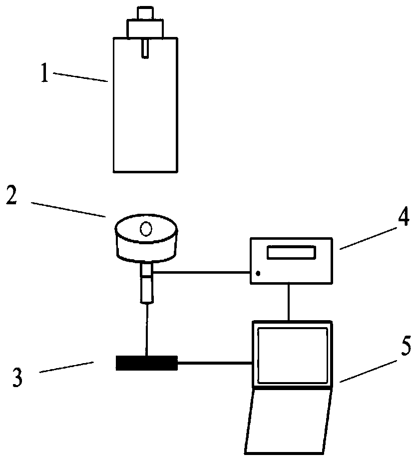
[0033] Embodiment one: if figure 1 As shown, the electron gun beam spot performance measuring device provided in this embodiment includes a charge-controlled electron gun 1 , a Faraday cup 2 , a precision displacement stage 3 , a picoammeter 4 and a computer 5 .

[0034] The connection relationship among the various components is as follows: the charge control electron gun 1 is located above the Faraday cup 2 . The Faraday cup 2 is fixedly connected to the precision translation platform 3 and moves synchronously with the precision translation platform 3 . One end of the picoammeter 4 is connected with the Faraday cup 2, and the other end is communicated with the computer 5.

[0035] Specifically, the picoammeter 4 can be connected to the Faraday cup 3 through a BNC line, and the picoammeter 4 can communicate with the computer 5 by means of a general interface bus GPIB or a serial interface line RS-232.

[0036] The composition and function of each component are as follows: ...

Embodiment 2

[0050] Embodiment 2: This embodiment discloses a method for measuring the beam spot performance of an electron gun. The measurement method uses the device for measuring the beam spot performance of an electron gun described in Embodiment 1 to work, including the following steps:

[0051] Step 1, setting the working parameters of the charge control electron gun 1 , the working parameters include accelerating voltage, cathode current and grid voltage.

[0052] Step 2, when the indication of the picoammeter 4 basically does not change, the charge control electron gun 1 is in a stable working state, at this time, the movement of the precision displacement table 3 is controlled, and the Faraday cup 2 is moved to the center point of the electron beam spot directly below;

[0053] This step specifically includes:

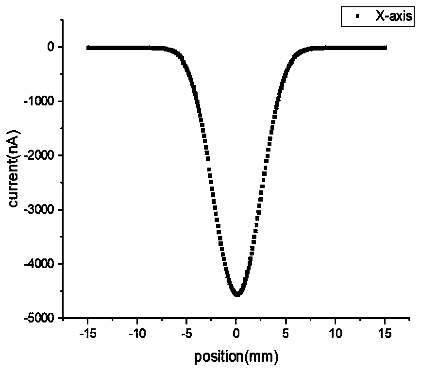
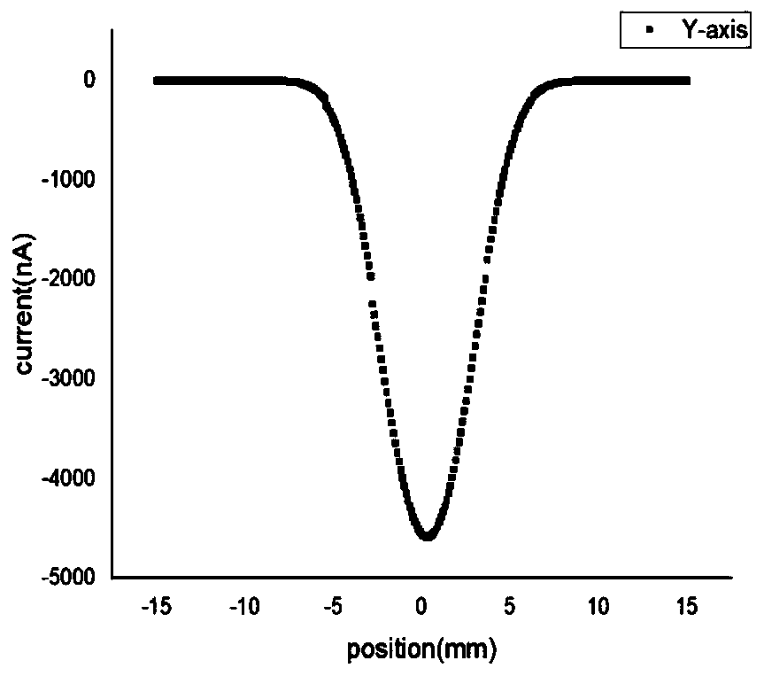
[0054] Step 2-1, controlling the movement of the precision translation stage 3 along the X-axis and the Y-axis, so that the Faraday cup 2 reaches near the center point of...


PUM


Abstract

The invention discloses a device and a method for measuring the beam spot performance of an electron gun. The measuring device comprises a charge control electron gun, a precision displacement table,a Faraday cup, a picoammeter and a computer. Measurement is carried out based on Faraday cup pinhole scanning. Important parameters of electron beam spot performance such as the beam spot diameter, the beam spot distribution characteristic diagram, the electron beam divergence angle and the like are obtained, therefore, comprehensive, accurate and deep analysis of the beam spots of the electron beams is realized, whether the electron beams generated by the electron gun meet the use requirements or not can be accurately judged, and the structure design optimization and installation and debugging of the electron gun are guided.

Description

technical field [0001] The invention relates to the technical field of electron beam performance measurement, in particular to a measuring device and method for measuring the beam spot performance of an electron gun. Background technique [0002] With the development of electronic technology, scanning electron microscope (SEM) plays an increasingly important role in scientific research and practical work. Today, the biggest bottleneck encountered by SEM in the characterization of material morphology is: due to the poor conductivity of non-metallic materials and organic materials, the incident charge and outgoing charge are not conserved, which leads to the charging phenomenon caused by charge accumulation. The charging phenomenon will form a space electric field on the surface and inside of the sample, and then dynamically affect the generation, transport and emission process of secondary electrons (SE), thereby affecting the image contrast information, usually resulting in ...

Claims


Application Information

Patent Timeline
Patent Type & Authority Applications(China)
IPC IPC(8): G01T1/29
CPCG01T1/29
Inventor 王岩邓晨晖赵伟霞殷伯华刘俊标韩立
Owner INST OF ELECTRICAL ENG CHINESE ACAD OF SCI
Why Eureka
Try Eureka