Power grid temperature monitoring method based on distributed type fiber bragg grating

A distributed optical fiber and grating technology, applied in temperature control, electrical program control, non-electric variable control, etc., can solve problems such as inability to play intuitive, fast, comprehensive understanding and control of the overall situation

Active Publication Date: 2012-02-08
安徽世听科技有限公司
View PDF0 Cites 0 Cited by
  • Summary
  • Abstract
  • Description
  • Claims
  • Application Information

AI Technical Summary

Problems solved by technology

[0005] With the popularization of distributed optical fiber temperature sensing in smart grids, the previous simple independent temperature sensors and their networks, as well as various automatic monitoring, independent operation, independent display and other characteristics make it impossible to play an intuitive, fast, comprehensive understanding and control of the overall situation. effect

Method used


Image

  • Power grid temperature monitoring method based on distributed type fiber bragg grating
  • Power grid temperature monitoring method based on distributed type fiber bragg grating
  • Power grid temperature monitoring method based on distributed type fiber bragg grating

Examples


Embodiment Construction

[0031] In order to make the purpose, technical solutions and advantages of the present invention clearer, the embodiments of the present invention will be further described in detail below in conjunction with the accompanying drawings:

[0032] This example provides a temperature monitoring method based on distributed fiber Bragg grating grid.

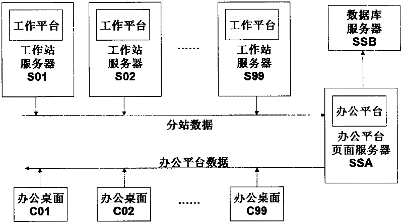
[0033] see figure 1 , showing the structure of a distributed FBG-based grid temperature monitoring method. The structure mainly includes: workstation platform and office platform. The workstation platform is a method of CS architecture. It is deployed on S01, S02, ... S99 on the workstation servers attached to each power station, and needs to be used synchronously with the corresponding pre-deployed related hardware instruments of each power station. After the workstation platform collects and analyzes the temperature information by manipulating the hardware, it transmits the information to the web server (SSA) attached to the office...


PUM


Abstract

The invention discloses a power grid temperature monitoring method based on a distributed type fiber bragg grating, comprising the following step of: arranging two platforms: a workstation platform and an office platform, wherein the workstation platform comprises a data processing module, a temperature monitoring module, an administrator module, an acousto-optic early-warning module, a laser filter control module, an AD (Analog to Digital) acquisition module and an optical debugging module; the office platform comprises an information integration module, a site information module, a real-time monitoring module, a remote management module, a history module, a report preprocessing module and a report exhibition module; and the workstation platform and the office platform share a databank and a memory module. The invention establishes a uniform real-time communication system and an integrated temperature and environment automatic monitoring system and realizes the concentration exhibition and the substation exhibition of temperature monitoring objects of a high-voltage device and the exhibition of real-time data curve and a graph report.

Description

technical field [0001] The invention relates to the field of fiber grating sensing, in particular to a temperature monitoring method based on distributed fiber grating power grids. Background technique [0002] As early as 1978, when Hill KO and others of the Canadian Communication Center first used the standing wave writing method in the germanium-doped optical fiber to make a fiber Bragg grating (FBG), the United States, Europe and other countries and regions became the scientific research center for fiber grating sensors and sensing technology. and technology development hotspots. [0003] Fiber Bragg grating sensing technology is a high-tech photoelectric sensing technology that has been applied and developed very rapidly in recent years. class of physical quantities. [0004] Since fiber grating sensing technology has achieved many key technological breakthroughs in engineering applications, this technology has been successfully applied to the safety detection of buil...

Claims


Application Information

Patent Timeline
Patent Type & Authority Patents(China)
IPC IPC(8): G05D23/20G05B19/418
CPCY02P90/02
Inventor 蒋祺刘炜江寅
Owner 安徽世听科技有限公司
Why Eureka
Try Eureka