Radio frequency remote equipment and distributed base station

A technology of radio remote equipment and distributed base stations, which is applied in radio relay systems, network planning, electrical components, etc., and can solve problems such as the unfavorable smooth evolution of GSM base stations

Active Publication Date: 2010-12-22
ALCATEL LUCENT SHANGHAI BELL CO LTD
View PDF0 Cites 4 Cited by
  • Summary
  • Abstract
  • Description
  • Claims
  • Application Information

AI Technical Summary

Problems solved by technology

This requires a separate development of a BBU+RRH for GSM, which is n

Method used


Image

  • Radio frequency remote equipment and distributed base station
  • Radio frequency remote equipment and distributed base station
  • Radio frequency remote equipment and distributed base station

Examples


no. 1 example

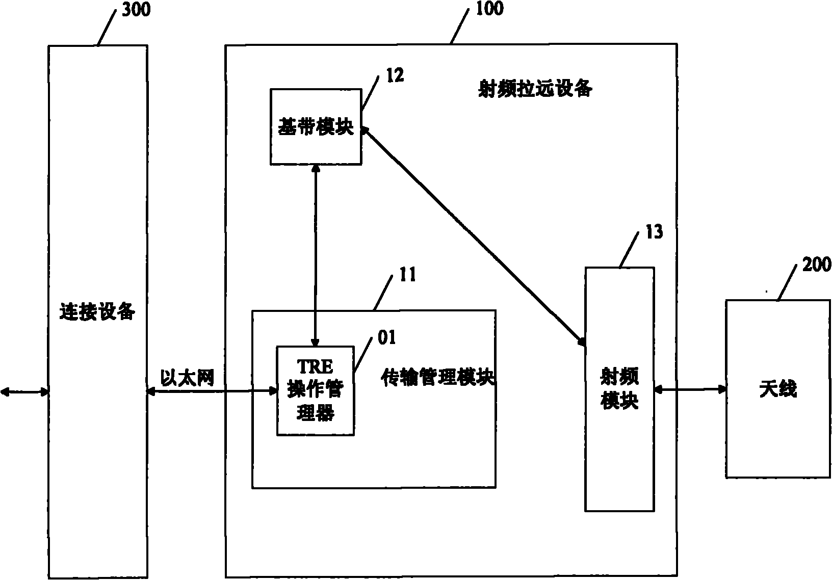
[0025] figure 1 The structure of the distributed GSM base station according to the first embodiment of the present invention is shown. The distributed base station in this embodiment includes an antenna 200 , a radio remote device 100 and a connection device 300 . In this embodiment, the GSM remote radio device 100 and the connection device 300 are connected through Ethernet. The radio remote device 100 is located at the far end, for example, installed on the antenna side, and the connection device 300 is located at the near end, for example, installed in the equipment room.

[0026] The remote radio device 100 includes a transmission management module 11 , a baseband module 12 and a radio frequency module 13 .

[0027] Such as Figure 7 As shown, during the sending operation, the connection device 300 transmits the GSM data from the base station controller (not shown) to the transmission management module 11 through Ethernet, and the transmission management module 11 proce...

no. 2 example

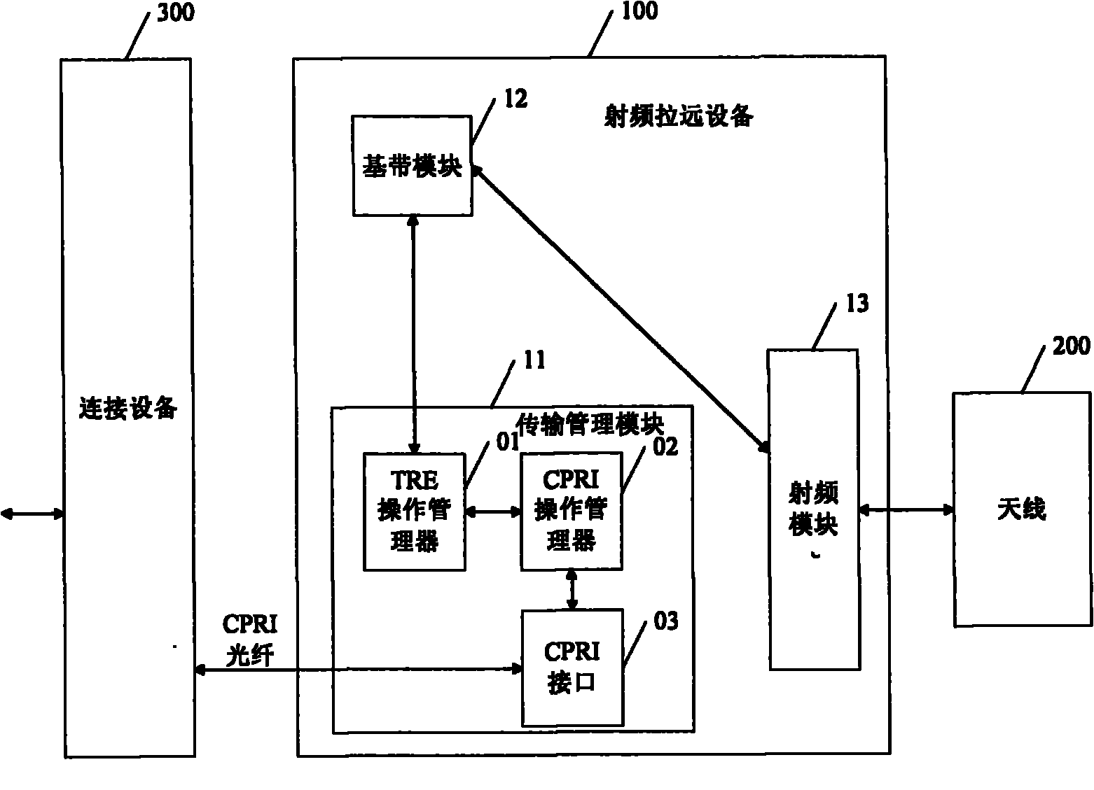
[0035] figure 2 The structure of the distributed GSM base station according to the second embodiment of the present invention is shown. The radio remote device 100 is located at the far end, for example, installed on the antenna side, and the connection device 300 is located at the near end, for example, installed in the equipment room.

[0036] The difference between the second embodiment and the first embodiment is that, in the second embodiment, the radio remote device 100 is connected to the connection device 300 through a CPRI optical fiber. In this case, the transmission management module 11 in the radio remote device 100 includes: a TRE operation manager (TREO&M) 01 , a CPRI operation manager (CPRI O&M) 02 and a CPRI interface 03 .

[0037] During the sending operation, the GSM data passes through the connecting device 300 from the base station controller to the CPRI interface 03 via the CPRI optical fiber, and then reaches the CPRI operation manager 02 through the CP...

no. 3 example

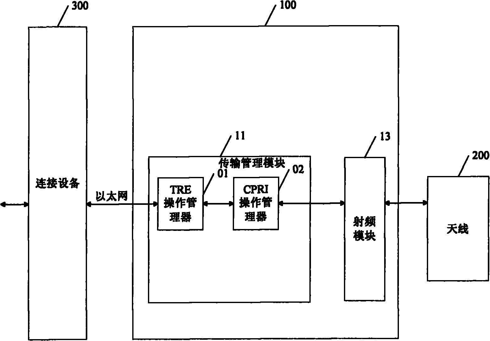
[0041] image 3 The structure of the multi-standard distributed base station according to the third embodiment of the present invention is shown. The distributed base station in this embodiment is suitable for processing other standard data besides GSM data, such as LTE data and UMTS data and so on. Similar to the first embodiment, in this embodiment, the distributed base station includes an antenna 200 , a radio remote device 100 and a connection device 300 . The GSM remote radio device 100 is connected to the connection device 300 through Ethernet. The radio remote device 100 is located at the far end, for example, installed on the antenna side, and the connection device 300 is located at the near end, for example, installed in the equipment room. The radio remote device 100 includes a transmission management module 11 and a radio frequency module 13 .

[0042] The difference from the first embodiment is:

[0043] 1. Because this embodiment is aimed at other standards, t...


PUM


Abstract

The invention provides radio frequency remote equipment and a distributed base station. In the distributed base station, while sending an operation, the radio frequency remote equipment receives first standard data and processes the first standard data into first transmission data, the first transmission data is subjected to base band processing to obtain second transmission data, and then the second transmission data is subjected to radio frequency processing to obtain an antenna signal; and while receiving the operation, the ratio frequency remote equipment carries out reverse radio frequency processing on the antenna signal received by an antenna to obtain the second transmission data, the obtained second transmission data is subjected to the reverse base band processing to obtain the first transmission data; and the first transmission data obtained by the reverse base band processing is processed into the first standard data.

Description

technical field [0001] The present invention relates to the technical field of mobile communication, in particular to a remote radio equipment used in a distributed base station and a distributed base station using the remote radio equipment. Background technique [0002] In the field of mobile communications, distributed base stations have become a key consideration for mobile operators worldwide in deploying mobile networks. The remote radio unit (RRH, RadioRemote Unit) is connected to the baseband unit (BBU, Base Band Unit) through optical fiber. , so that the radio frequency unit is no longer limited by the environment of the computer room. Compared with traditional solutions, the cost of network construction is greatly reduced, while the time for network deployment is greatly shortened, representing a milestone in the development of mobile communication base station technology. At present, distributed base station solutions have been fully introduced in WCDMA, CDMA2000...

Claims


Application Information

Patent Timeline
IPC IPC(8): H04W16/26H04W88/08H04B7/14
Inventor 汪雁徐颂华倪冬明邵鸣怡苏波
Owner ALCATEL LUCENT SHANGHAI BELL CO LTD
Why Eureka
Try Eureka