
LED constant current circuit and method

A technology of constant current circuit and LED lamp, which is applied in the direction of electric lamp circuit layout, electric light source, lighting device, etc. It can solve the problems of input signal pulse interference, constant current chip cannot match different power LED lamps, etc., to reduce interference and use flexible effects

Active Publication Date: 2013-03-27
OCEANS KING LIGHTING SCI&TECH CO LTD +1
View PDF2 Cites 0 Cited by
  • Summary
  • Abstract
  • Description
  • Claims
  • Application Information

AI Technical Summary

Problems solved by technology

[0004] The technical problem to be solved by the present invention is to provide an LED lamp driver capable of resisting transient high-energy pulse interference and providing constant current drive for the defects that ordinary constant current chips cannot match different power LED lamps and the input signal is easily affected by pulse interference. circuit and method

Method used


Image

  • LED constant current circuit and method
  • LED constant current circuit and method
  • LED constant current circuit and method

Examples


Embodiment Construction

[0024] The present invention will be further described below in conjunction with the accompanying drawings.

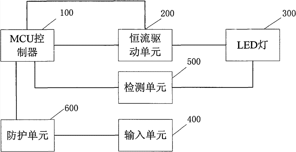
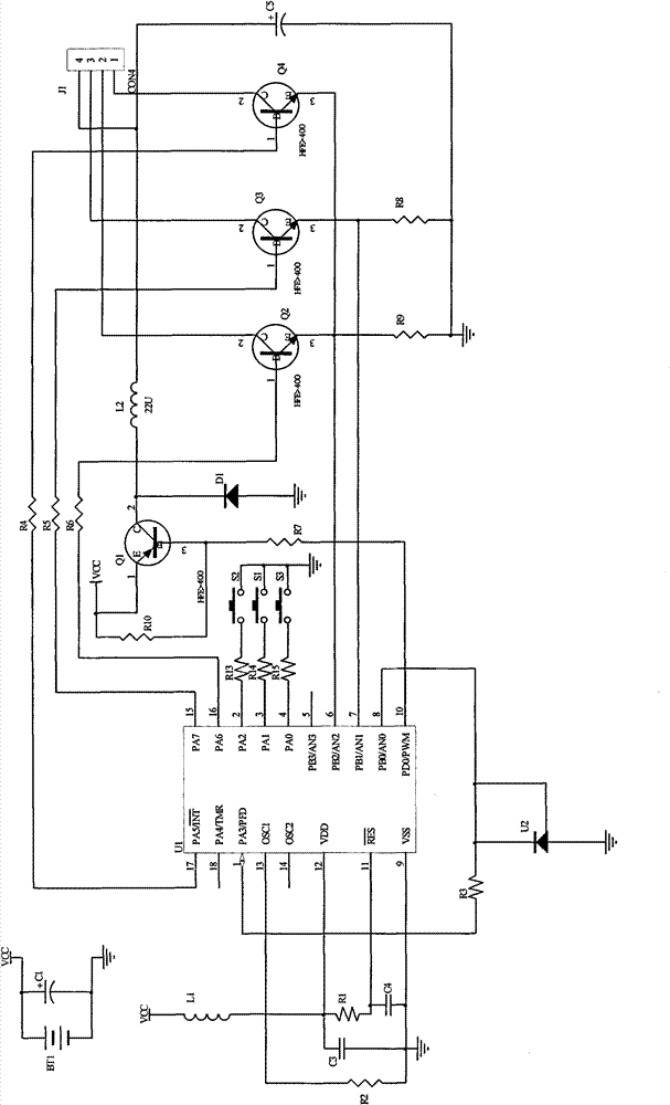
[0025] figure 2 It is a structural schematic diagram of an embodiment of an LED constant current circuit in the present invention. The circuit includes an MCU controller 100, a constant current drive unit 200, an LED lamp 300, an input unit 400, and also includes a detection unit 500 connected to the LED lamp 300 to collect the current or voltage signal of the LED lamp 300, and generates a signal for the input unit 400. The protection unit 600 that filters the switch signal; the MCU controller 100 generates an LED light switch control signal based on the filtered switch signal output by the protection unit 600, and controls the LED light 300 to turn on and off through the constant current drive unit 200; The MCU controller 100 outputs PWM waves with a duty cycle from low to high one by one, and sequentially supplies power to the LED lamp 300 through the constant curr...


PUM


Abstract

The invention provides an LED constant current circuit which comprises an MCU controller, a constant current driving unit, an LED lamp, an input unit and a detecting unit, wherein the detecting unit collects current or voltage signals of the LED lamp; and the MCU controller outputs PWM waves with gradually increased duty ratios one by one, analyzes and determines the minimum value of the duty ratio of the PWM waves when the current or voltage of the LED lamp is the maximum, regularly outputs the PWM waves, and enables the LED lamp to normally light through the constant current driving unit. The invention also provides an LED constant current method. The circuit and the implementation method of the invention can resist transient high-energy pulse interference, solves the problem of generating error signals due to interference, realizes precise constant current and adjustable constant current, and enables the LED lamp to light with constant illuminance.

Description

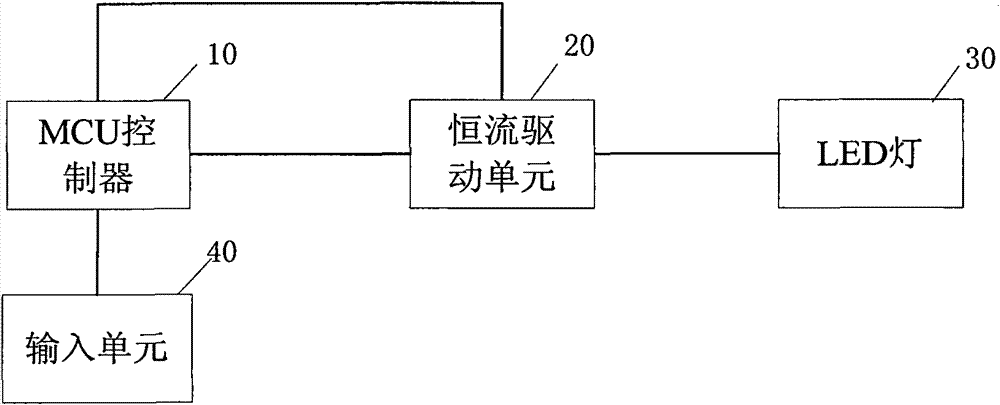
technical field [0001] The present invention relates to an illumination control circuit and method, more specifically, to a constant current circuit and method for LED lamps. Background technique [0002] The driving circuit of the existing LED lamp such as figure 1 As shown, it includes an MCU controller 10 , a constant current drive unit 20 , and an LED lamp 30 . The MCU controller 10 outputs a fixed PWM wave to the constant current drive unit 20. The constant current drive unit 20 inverts the DC power into AC power, and then outputs a constant current to drive the LED lamp 30 to realize normal light emission of the LED lamp. At present, constant current drive units generally use constant current chips, and constant current chips generally have a type that can only output a fixed current. When LED lamps with different powers are replaced, the required driving current will change, so ordinary constant current chips cannot meet the requirements, and more expensive adjustab...

Claims


Application Information

Patent Timeline
Patent Type & Authority Patents(China)
IPC IPC(8): H05B37/00H05B37/02
Inventor 周明杰樊亮熊远恒
Owner OCEANS KING LIGHTING SCI&TECH CO LTD
Learn More