Imaging body and imaging device having the same

A technology for imaging devices and main parts, which can be used in developing and printing devices, projection devices, image communication, etc., and can solve problems such as the inability to use imaging components

Inactive Publication Date: 2010-12-22
OLYMPUS CORP
View PDF1 Cites 0 Cited by
  • Summary
  • Abstract
  • Description
  • Claims
  • Application Information

AI Technical Summary

Problems solved by technology

Therefore, it is not possible to use an image sensor with a large light-receiving part

Method used


Image

  • Imaging body and imaging device having the same
  • Imaging body and imaging device having the same
  • Imaging body and imaging device having the same

Examples


Embodiment Construction

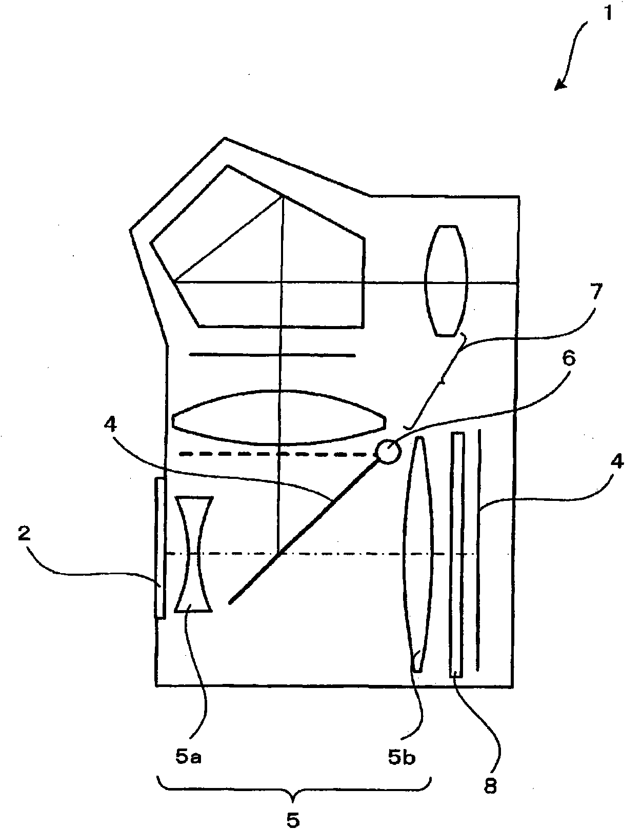
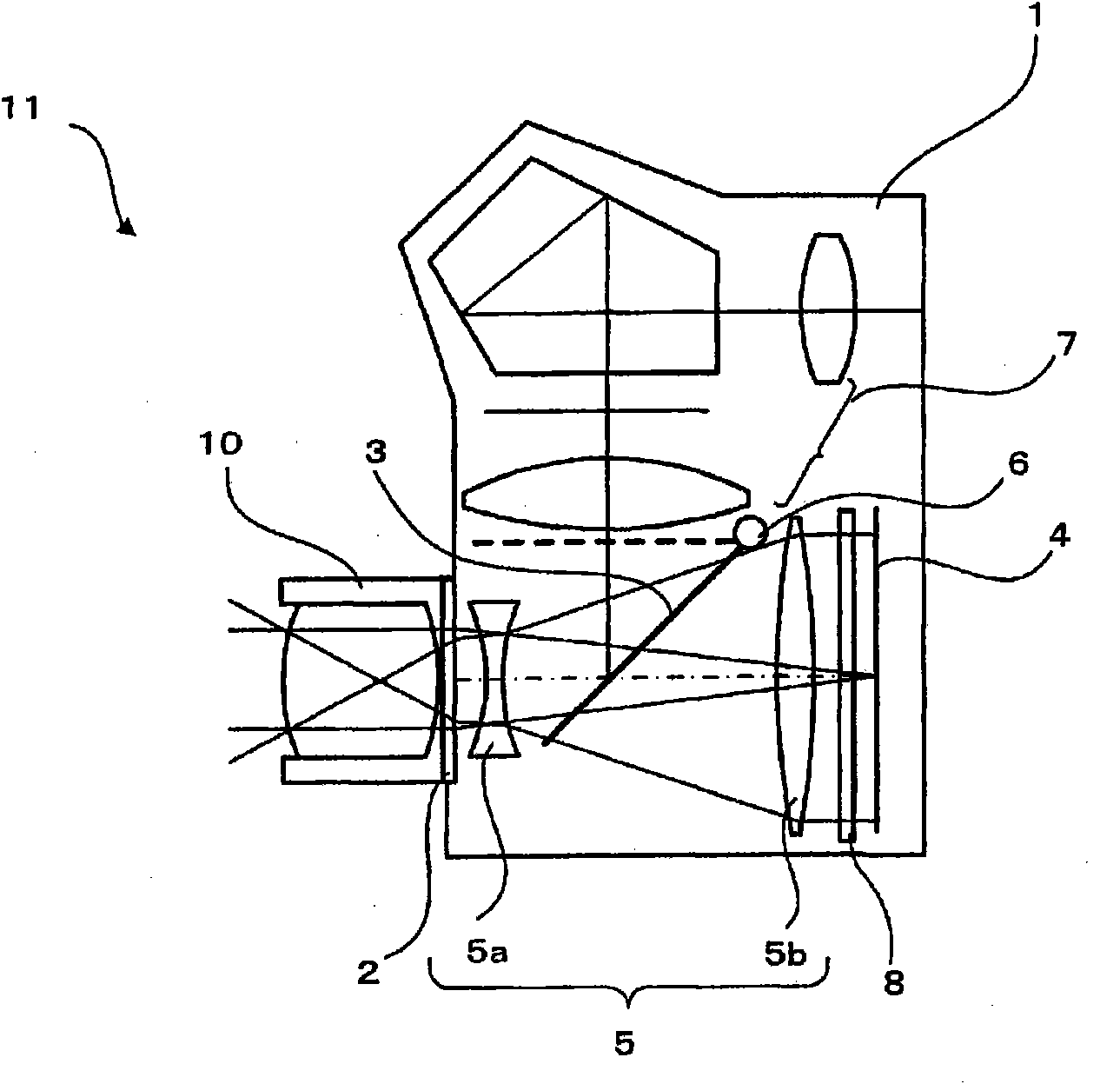
[0027] Embodiments of the present invention will be described. figure 1 The camera body unit of this embodiment is shown in . exist figure 1 Among them, the imaging main body unit 1 has a detachable unit 2 , an optical path division unit 3 , an imaging element 4 , a conversion optical system 5 , a moving mechanism 6 , and a finder optical system 7 . The detachable part 2 is, for example, a bayonet ring. The photographic optical system can be attached and detached via the attachment and detachment unit 2 .

[0028] The optical path dividing unit 3 is, for example, a mirror (quick return mirror). The mirror can be moved to the first position and the second position by the moving mechanism 6 . The first position is the position shown by the solid line. The first position is between the attachment and detachment unit 2 and the imaging element 4 . Also, the second position is a position indicated by a dotted line. The second position is a position obtained by rotating the op...


PUM


Abstract

An imaging body (1) includes: an attach / detach portion (2) to which an imaging optical system is detachably attached; optical path division means (3); an imaging element (4); and a conversion optical system (5, 5'). The conversion optical system (5, 5') is formed by a front lens system (5a, 5c, 5d) and a rear lens system (5b, 5e). The front lens system (5a, 5c, 5d) is arranged between the attach / detach portion (2) and the optical path division means (3). The rear lens system (5b, 5e) is arranged between the optical path division means (3) and the imaging element (4).

Description

technical field [0001] The present invention relates to an imaging main unit and an imaging device with a detachable imaging optical system. Background technique [0002] There is known a camera in which an imaging element can be replaced with an imaging element of a different size depending on the purpose of photography (see Patent Document 1). This camera includes a substantially horizontally long box-shaped camera body and a photographing lens for a silver salt single-lens reflex camera. The camera body is directly converted to a camera body for a silver halide single-lens reflex camera. As the back cover, there are a back cover for a silver halide camera and a back cover for a digital camera. Furthermore, the back cover for a digital camera can be attached to a camera main body, and it can be used as a digital camera by this. Furthermore, the CCD substrate can be replaced. Thereby, different digital cameras can be configured with one camera body 2 . [0003] Patent ...

Claims


Application Information

Patent Timeline
IPC IPC(8): G03B19/06G02B13/02G03B17/28G03B19/12H04N5/225
CPCG03B5/06G03B19/12H04N5/2254G02B15/10G03B13/06H04N23/55
Inventor 中野俊文铃木达哉后藤尚志
Owner OLYMPUS CORP
Why Eureka
Try Eureka