Phototherapy Device and Method of Providing Phototherapy to a Body Surface

a technology of phototherapy and body surface, which is applied in the field of phototherapy devices and methods of providing phototherapy to the body surface, can solve the problems of undesirable large size of lasers and bulb light sources, no small portable devices currently available to deliver this type of treatment, and damage to the skin that was originally normal and healthy, and achieves the effect of small siz

Inactive Publication Date: 2007-09-06
VALAM CORP
View PDF101 Cites 264 Cited by
  • Summary
  • Abstract
  • Description
  • Claims
  • Application Information

AI Technical Summary

Benefits of technology

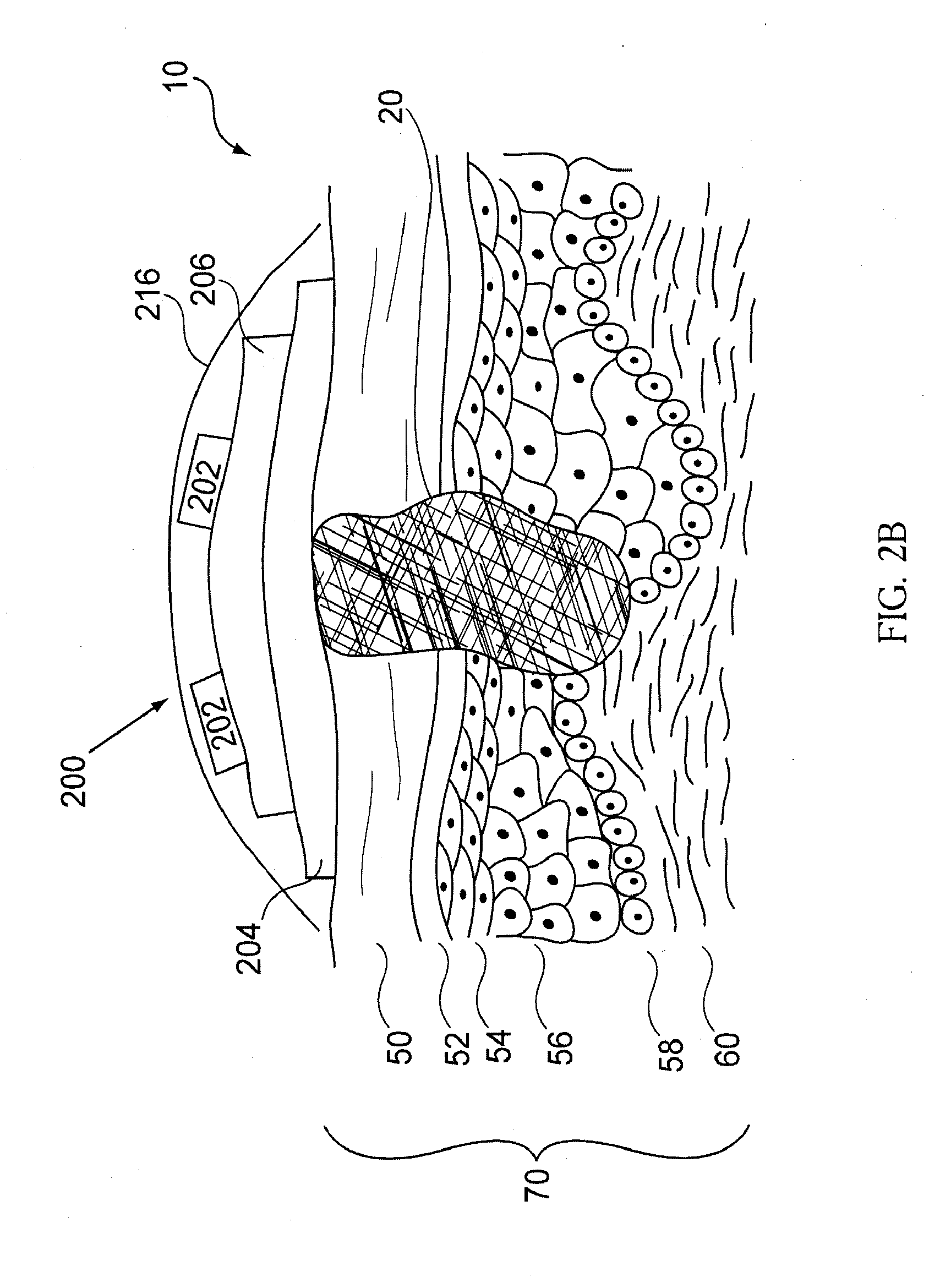
[0014] Still further in accordance with the described invention, the device is intended to be securely attached to a patient via an adhesive, a strap, or other mechanism such that the recipient of the therapy is minimally encumbered during treatment. Additionally, light sources are controlled by a small microprocessor and powered by a battery. The combination of the preceding two qualities enables the patient to, for example, be free to move about during treatment.
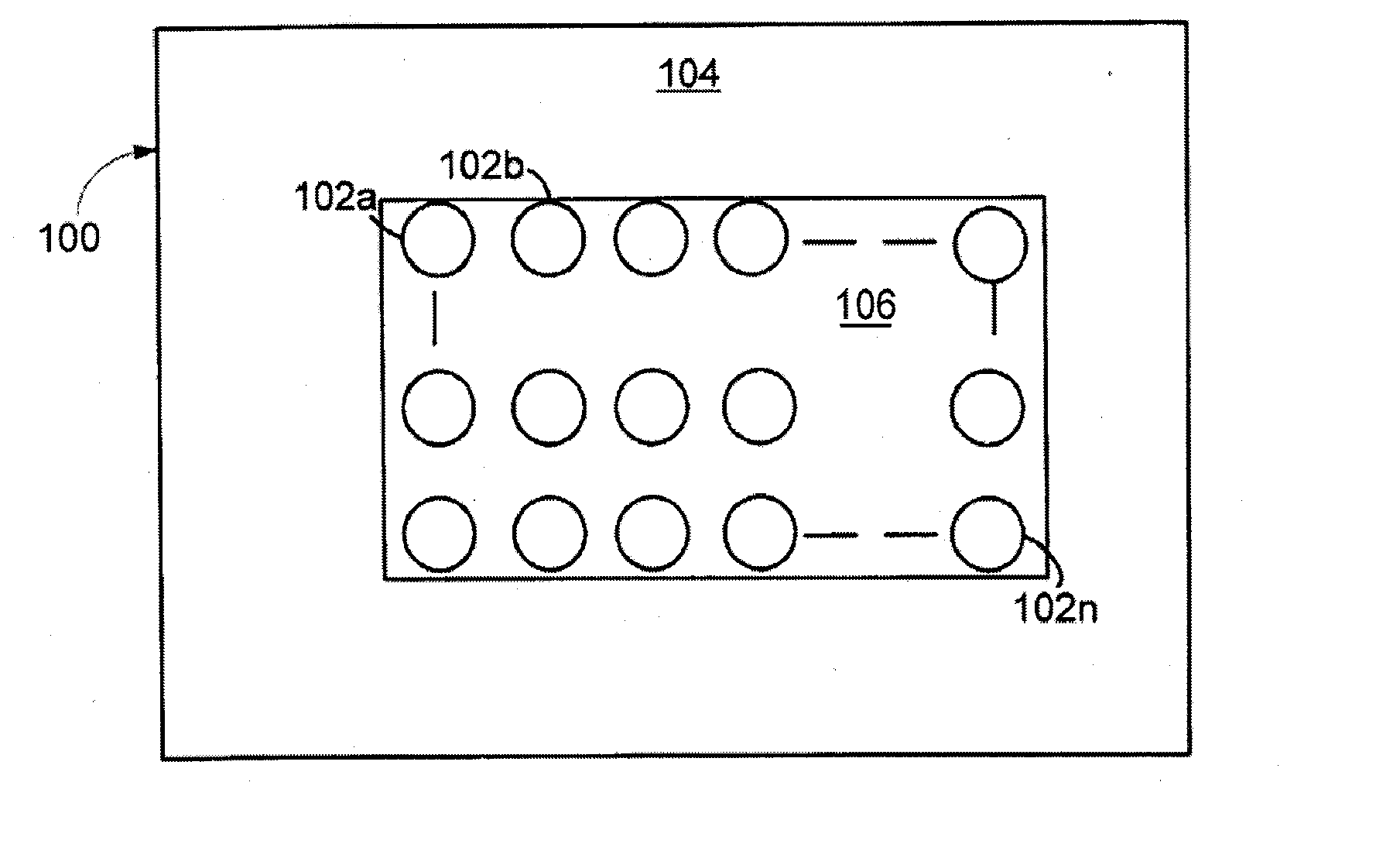
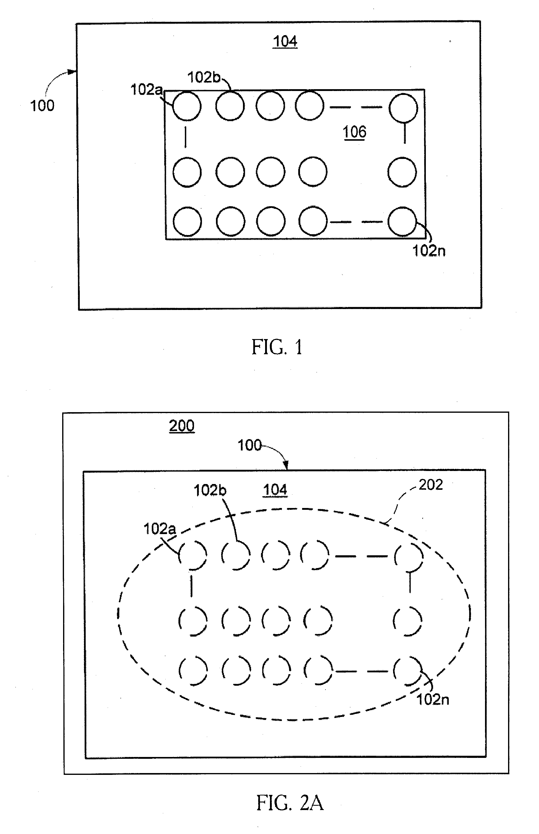
[0015] Still further in accordance with the described invention, the light delivery element is in part composed of rigid or semi-rigid optical integrator elements that are in intimate contact with the body surface and adhered to a flexible substrate. One or more light sources are associated with each of these optical integrator elements. The optical transmission properties of each integrator element are such that a uniform light distribution is transmitted to the body surface in which it is in contact. The spacing and configuration geometry of the light integrator elements essentially determine the total body surface area receiving treatment. Therefore, the ensemble effect of such elements on a flexible substrate is to substantially conform to a body surface as well as deliver a uniform therapeutic treatment over the same surface.
[0016] Still further in accordance with the described invention is an intermediary targeting mask to be used in concert with the phototherapy delivery element. This targeting mask is used in regions where an affected area is irregular in shape and overall smaller in size as compared to the therapy device. Its function is to be placed in between the device and the body surface and selectively expose affected surface areas to the phototherapy treatment while simultaneously minimizing or eliminating such a treatment light from reaching unaffected neighboring regions of healthy skin surface. Still further in accordance with the described invention is the ability to detect the zone for treatment and subsequently power a subset of the light sources on the phototherapy delivery element.

Problems solved by technology

However, there are no small, portable devices currently available to deliver this type of treatment.
In this type of treatment, areas of healthy skin are also exposed to the treatment dose which may cumulatively lead to damage to skin that was originally normal and healthy.
Additionally, lasers and bulb light sources are undesirably large.
In a clinic, they reduce available space for other medical equipment.
Additionally, these light sources can be prohibitively expensive.

Method used


Image

  • Phototherapy Device and Method of Providing Phototherapy to a Body Surface
  • Phototherapy Device and Method of Providing Phototherapy to a Body Surface
  • Phototherapy Device and Method of Providing Phototherapy to a Body Surface

Examples


example 1

[0169] A ray tracing calculation was performed to show the effect of a light integrator on the uniformity of the output power at the exit plane of the device.

[0170] The resulting output of four LED emitters to a flat body surface was simulated. The four LEDs are positioned on a square grid with an 11.5 mm spacing between the centers of each LED. The distance to the body surface is 5.5 mm. The integrators consist of silicone rubber geometrical shapes that are approximately cuboid in structure with rounded edges and corners. For simulation purposes, the refractive index of such transparent structures was set to 1.5. The size of the integrators is 10×10×4 millimeters, and the edges are rounded with a radius of 1 mm. There is a negative lens incorporated into the top side of the integrator element which faces towards each respective LED. The radius of this lens is 1 mm. A schematic diagram from an approximately ¾ viewpoint is depicted in FIG. 24. The LED's are assumed to be Lambertian ...


PUM


Abstract

A method and apparatus is described for treating a target body surface using a radiation applicator. The therapeutic treatment apparatus adapted to conform to a patients body. The treatment apparatus comprises a plurality of light sources coupled with a flexible substrate, a light integrator in at least a portion of the optical path between the light source and the patient's body surface, a power supply, and a controller.

Description

CROSS-REFERENCE [0001] This application is a continuation-in-part application of Ser. No. 11 / 276,787 filed Mar. 14, 2006, which in turn is a continuation-in-part application of Ser. No. 11 / 244,812, filed Oct. 5, 2005, which are incorporated herein by reference in their entirety and to which application priority is claimed under 35 U.S.C. §120. This application also claims benefit of U.S. Provisional Application No. 60 / 882,439 filed Dec. 28, 2006, which is also incorporated herein by reference in its entirety.BACKGROUND OF THE INVENTION [0002] 1. Field of the Invention [0003] The invention relates to devices and methods of use for small, portable devices adapted and configured to deliver phototherapeutic treatments to a select area of a skin surface to treat medical skin disorders or to perform cosmetic dermatological therapies. More specifically, the devices comprise a plurality of light sources and are flexible such that the devices are adapted to conform to a body surface while pr...

Claims


Application Information

Patent Timeline
Patent Type & Authority Applications(United States)
IPC IPC(8): A61N5/06
CPCA61N5/0616A61N5/062A61N2005/007A61N2005/0645A61N2005/0652A61N2005/063A61B2017/00026A61B2017/00057A61B2018/00642A61B2018/00702A61B2018/00785A61N2005/0628
Inventor LECLERC, NORBERT H.MORAN, BRENDAN JUDEFLOM, JAMES R.GERTNER, MICHAELPODMORE, JONATHAN L.RODE, MICHAELCROWE, JOHN E.ROGERS, ERICA
Owner VALAM CORP
Why Eureka
Try Eureka