Near-eye display with on-axis symmetry

a technology of symmetry and near-eye display, applied in the field of near-eye displays, can solve the problems of undesirable addition of thickness, and achieve the effect of reducing the problems of image distortion and chromatic aberration

Active Publication Date: 2013-02-19
VUZIX
View PDF26 Cites 271 Cited by
  • Summary
  • Abstract
  • Description
  • Claims
  • Application Information

AI Technical Summary

Benefits of technology

[0005]The invention among it preferred embodiments, features a near-eye display with a selectively reflective powered optic (also meant to be selectively transmissive as well) oriented nominally normal to a line of sight to the ambient environment. Optical paths to and from the selectively reflective powered optic effectively overlap. That is, although the optical path to the selectively reflective powered optic is folded to locate an image generator out of the line of sight, the image generator and the selectively reflective powered optic both remain nominally normal to local portions of the optical path between them. The common optical alignment between the image generator and the selectively reflective powered optic reduces issues of image distortion and chromatic aberration, largely by maintaining rotational symmetry.
[0006]In addition, the folded light path to the selectively reflective powered optic allows the image generator or its relayed image to be inclined (i.e., effectively inclined) to a thickness direction of the near-eye display along the line of sight. The inclined orientation of the image generator or its relayed image enables the construction of a thinner, i.e., more compact, near-eye display.
[0007]One version of a near-eye display in accordance with the invention projects virtual images from an image generator to an eyebox within which the virtual images can be seen by a viewer. A selectively reflective powered optic connects first and second optical paths. The first optical path conveys image-bearing light from the image generator to the selectively reflective powered optic, and the second optical path conveys the image-bearing light along a line of sight from the selectively reflective powered optic to the eyebox. First and second selectively reflective surfaces fold the first optical path with respect to the second optical path to locate the image generator out of the line of sight to the eyebox. The image generator is effectively inclined to the line of sight to the eyebox for reducing a thickness of the near-eye display, and the selectively reflective powered optic is oriented nominally normal to local overlapping portions of the first and second optical paths at the selectively reflective powered optic for reducing image distortion.
[0008]Preferably, the image generator is also oriented nominally normal to a local portion of the first optical path at the image generator for reducing image distortion. The first selectively reflective surface and the selectively reflective powered optic have optical axes preferably oriented substantially parallel to the line of sight along the second optical path. The second selectively reflective surface has an optical axis preferably oriented with respect to the axis of the first selectively reflective surface through an angle of less than 45 degrees and more preferably between 25 degrees and 35 degrees.

Problems solved by technology

Such additional thickness is often undesirable.

Method used


Image

  • Near-eye display with on-axis symmetry
  • Near-eye display with on-axis symmetry
  • Near-eye display with on-axis symmetry

Examples


Embodiment Construction

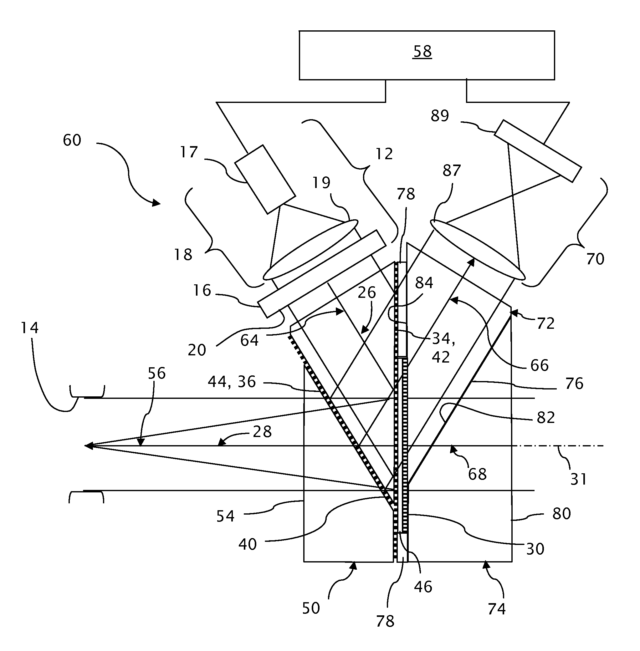
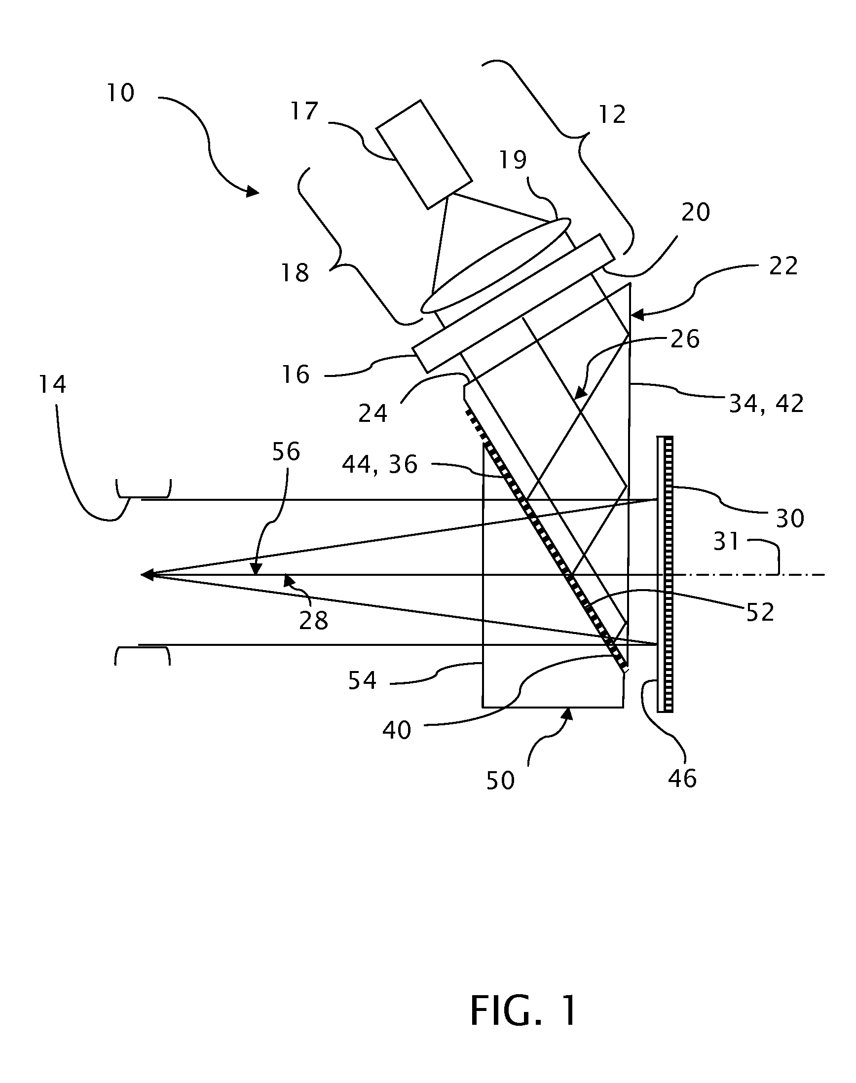
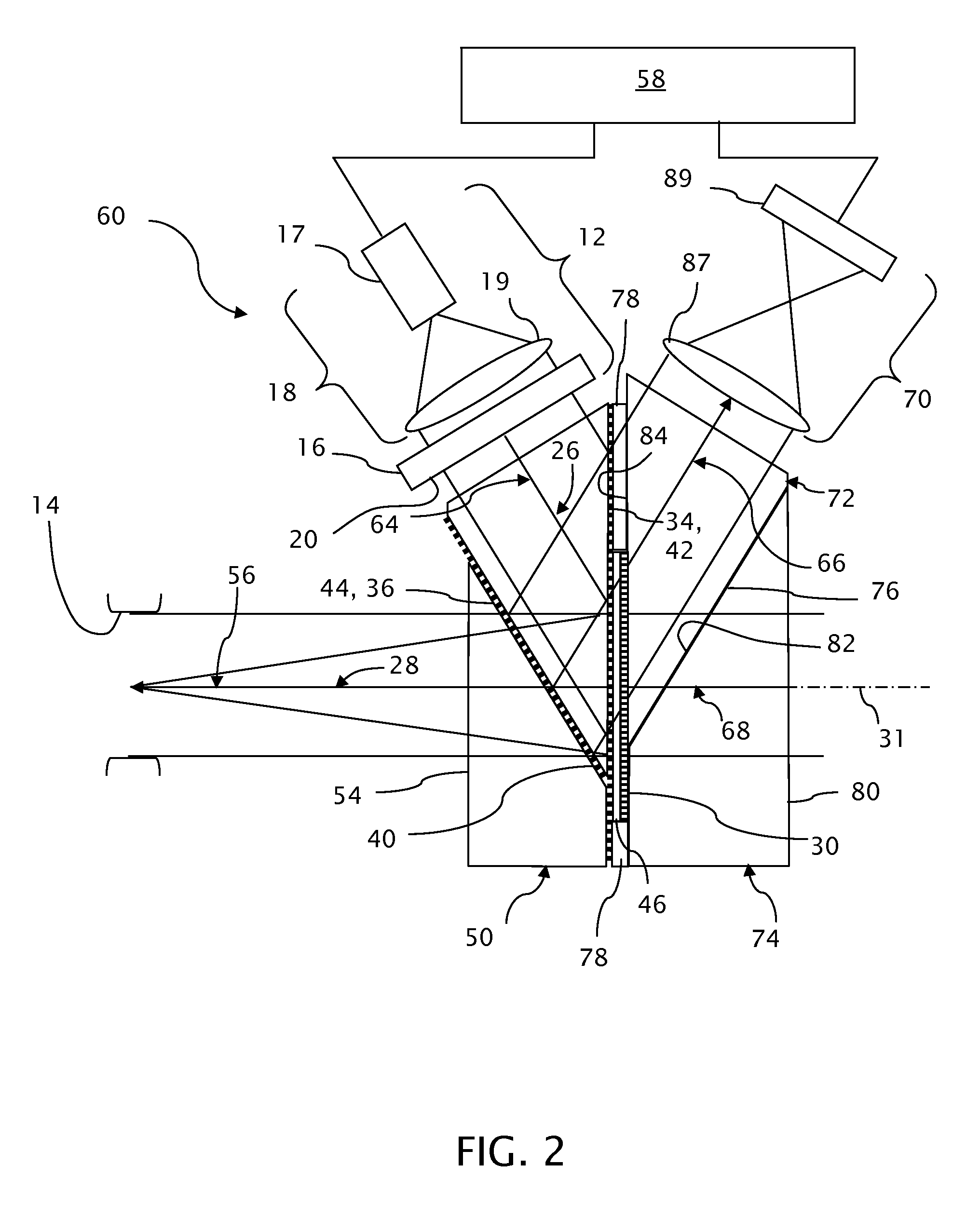
[0021]A near-eye display 10, as depicted in FIG. 1, includes an image generator 12 for producing a succession of images, such as video images, that are projected as virtual images into an eyebox 14. The image generator 12, which can take a number of forms, preferably combines a spatial light modulator 16 with an illuminator 18 that uniformly illuminates the spatial light modulator 16. The illuminator 18 preferably includes a light source 17, which can be formed by one or more light emitting diodes or other known sources including lamps, and a condenser 19 that collects light from the source 17 and evenly illuminates the spatial light modulator 16. Light patterns are produced within the spatial light modulator 16 by differentially propagating light on a pixel-by-pixel basis in accordance with a video input signal from a video source (not shown). For example, the spatial light modulator 16 can comprise a controllable array of liquid crystal diodes functioning as individually addressab...


PUM

PropertyMeasurementUnit
angleaaaaaaaaaa
angleaaaaaaaaaa
angleaaaaaaaaaa

Abstract

A near-eye display projects virtual images from an image generator to an eyebox within which the virtual images can be seen by a viewer. A first optical path conveys image-bearing light from the image generator to a selectively reflective powered optic and a second optical path conveys the image-bearing light along a line of sight from the selectively reflective powered optic to the eyebox. First and second selectively reflective surfaces fold the first optical path with respect to the second optical path to locate the image generator out of the line of sight to the eyebox. The image generator is effectively inclined to the line of sight to the eyebox for reducing a thickness of the near-eye display. The selectively reflective powered optic is oriented normal to local overlapping portions of the first and second optical paths at the selectively reflective powered optic.

Description

TECHNICAL FIELD[0001]Near-eye displays, which include helmet-mounted, head-mounted, and video eyewear displays, project virtual images generated by microdisplay engines into viewers' eyes. Augmented reality near-eye displays incorporate computer vision systems and project virtual computer-generated imagery atop see-through views of the ambient environment.BACKGROUND OF THE INVENTION[0002]Near-eye displays, particularly those that also provide see-through views of the ambient environment, incorporate powered optics for forming virtual images without unduly obstructing views of the ambient environment. Some such displays fold light paths to the powered optics out of the line of sight to the ambient environment and in others, the powered optics are at least partially transparent to light from the ambient environment.[0003]The powered optics folded out of the line of sight generally add to another dimension of the displays, particularly to the thickness of the displays. Such additional ...

Claims


Application Information

Patent Timeline
Patent Type & Authority Patents(United States)
IPC IPC(8): G03B21/14G02B27/22G02B5/32G03B21/28G03H1/26G02F1/1335G02F1/07G02F1/03
CPCG02B5/32G02B27/0101G02B2027/0112
Inventor SCHULTZ, ROBERT J.
Owner VUZIX
Why Eureka
Try Eureka