Ducted drying rack for clothes dryer

a drying rack and clothes dryer technology, applied in drying machines, drying chambers/containers, light and heating equipment, etc., can solve the problems of less efficient drying operation, slow drying speed, and still suffer from construction, so as to reduce the storage space required for the drying rack, reduce the height profile of storage, and facilitate storage space

Inactive Publication Date: 2009-06-30
MAYTAG
View PDF11 Cites 23 Cited by
  • Summary
  • Abstract
  • Description
  • Claims
  • Application Information

AI Technical Summary

Benefits of technology

[0013]A drying rack constructed in accordance with the present invention overcomes the disadvantages in the art by creating at least two paths for the normal stream of heated air in the clothes dryer. Additionally, the storage space required for the drying rack is reduced by providing a movable flap that can be placed in one position to create the desired airflow paths, and in a second position to provide a reduced height profile for storage. Further, a hook is also provided on the clothes dryer cabinet to create a convenient storage space for the drying rack when not in use.
[0017]Preferably, the drying rack mounting features are confined to the perforated tray. This allows for model differentiation by the manufacturer by providing the opportunity to utilize the perforated tray of the drying rack with or without the duct attached.

Problems solved by technology

One disadvantage of a drying rack such as the one mentioned above is that the heated airflow may pass through the drum without actually passing through the clothing.
The result is a slower, less-efficient drying operation than could otherwise be accomplished.
However, this construction still suffers from one or more of the following disadvantages.
One problem that is apparent is the situation where the clothing article to be dried substantially covers the entire gridwork of the rack, and reduces the airflow volume, thus increasing the temperature of the incoming air.
Further, the clothing placed on the drying rack creates an airflow restriction that is upstream from the controlling thermostats and delays the ability of the thermostats to react to rapidly rising temperatures.
This approach leaves ample room for consumer error.
Another disadvantage of the prior art ducted drying rack is that excessive storage space is required.
Consumers typically have little storage space in their laundry rooms, and since the drying rack is used infrequently, storage can become a nuisance.

Method used


Image

  • Ducted drying rack for clothes dryer
  • Ducted drying rack for clothes dryer
  • Ducted drying rack for clothes dryer

Examples


Embodiment Construction

[0030]The present invention will now be described as it applies to its preferred embodiment. While it is not intended that the present invention be limited to only the described embodiment, it is intended that the invention encompass all alternatives, modifications, and equivalencies apparent to those skilled in the art and that may be included within the spirit and scope of the invention.

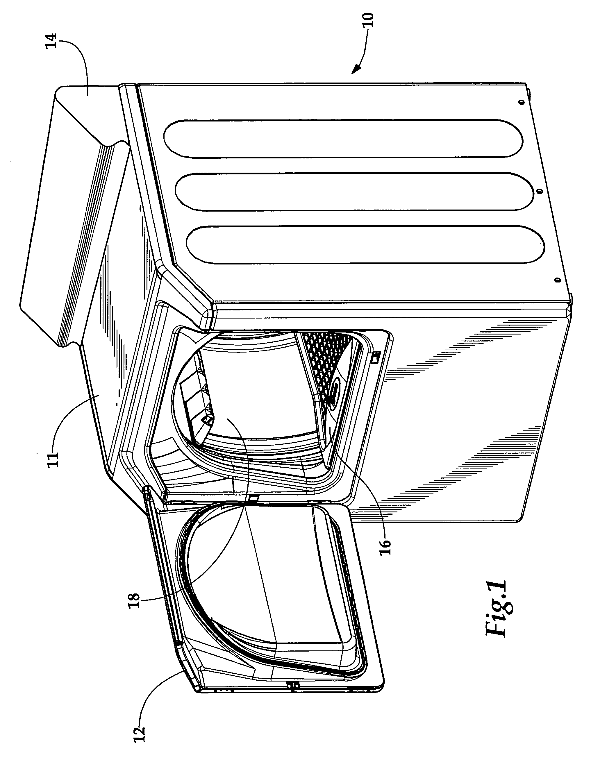
[0031]FIG. 1 shows a clothes dryer 10 including a top cover 11, an access door 12 and a control panel 14. The drying rack assembly 16 is shown assembled within the rotatable drum or tumbler 18.

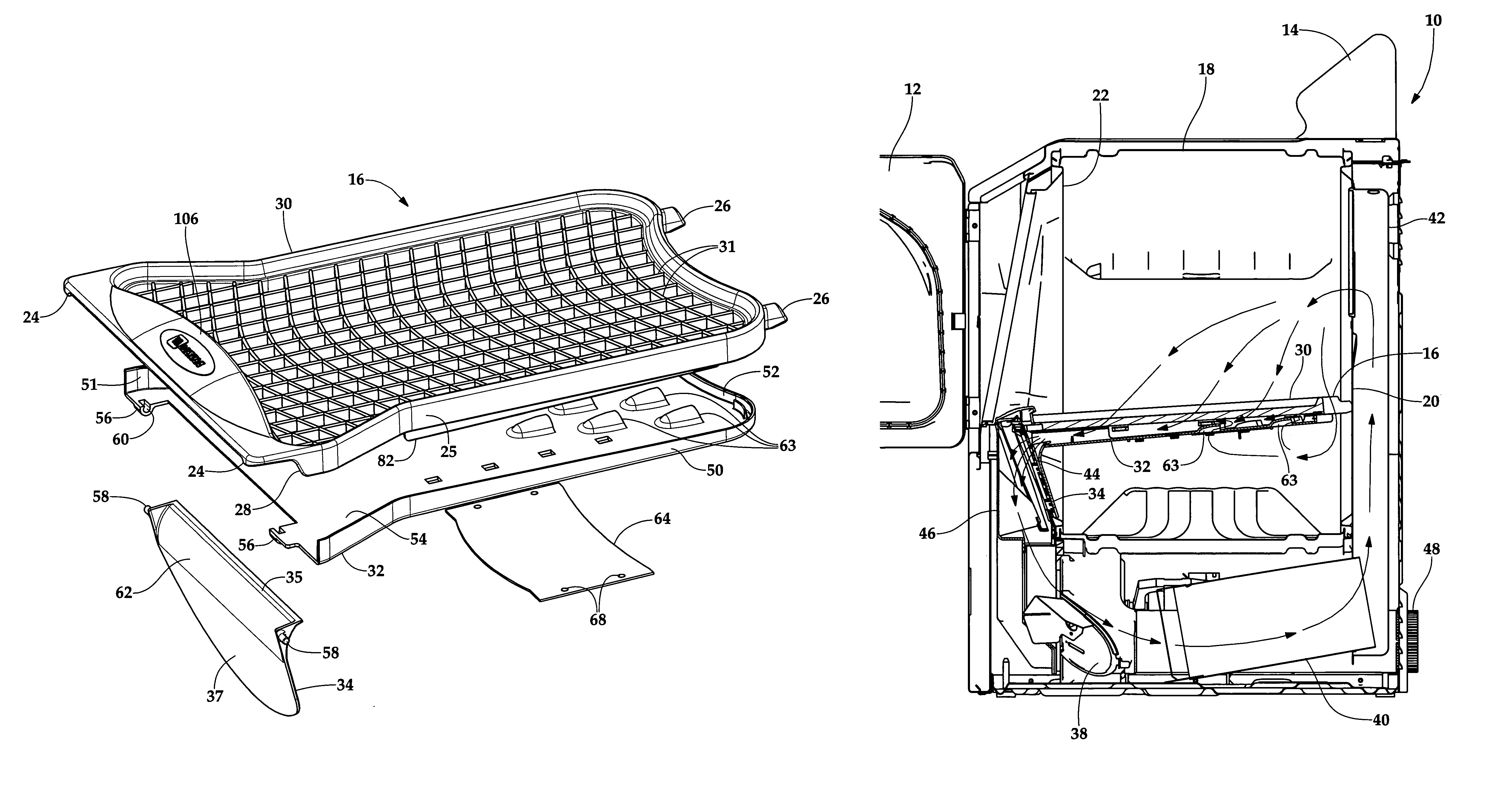
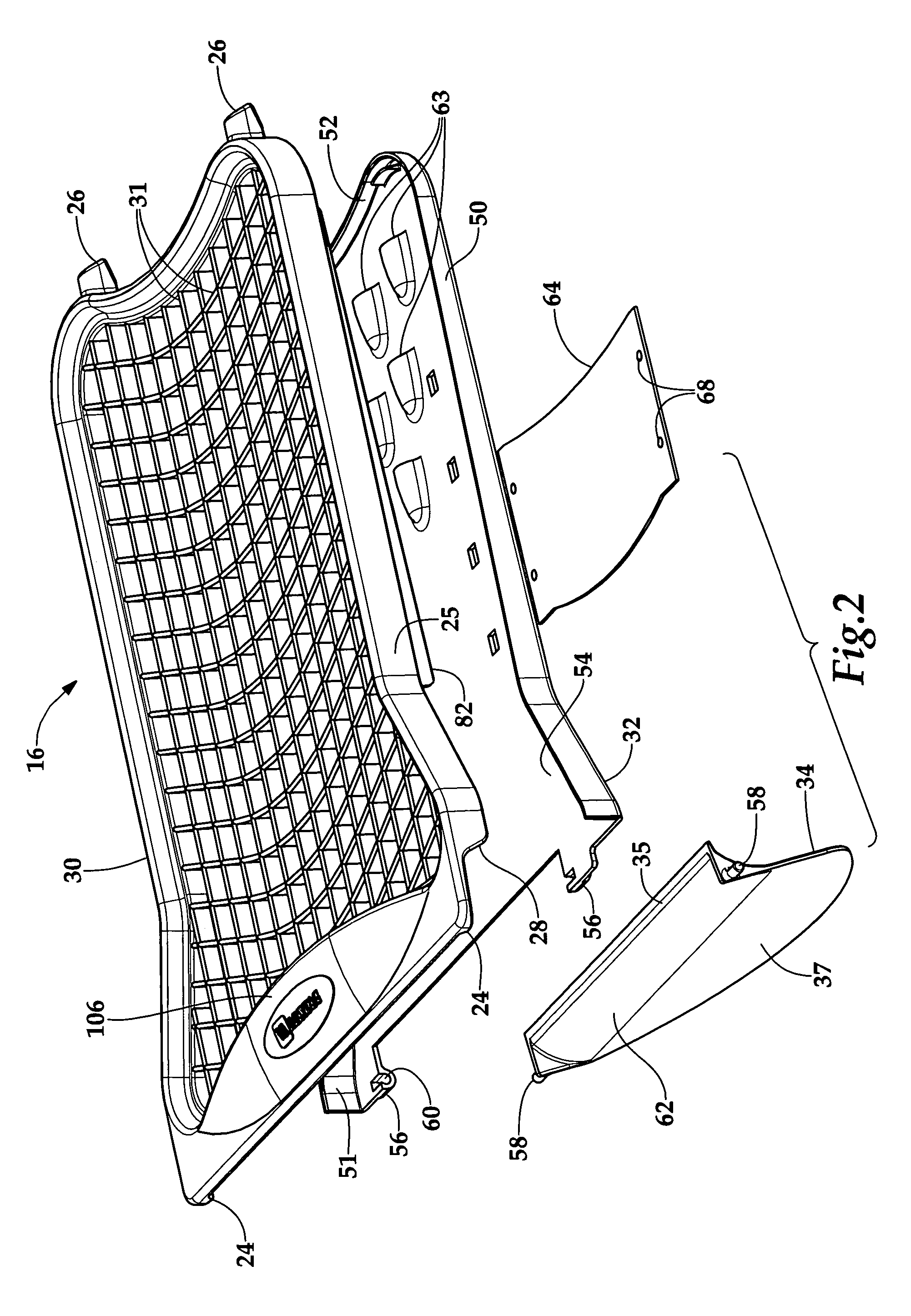
[0032]FIG. 2 displays the drying rack assembly 16 composed of a perforated tray 30, duct 32 and air outlet cover 34. The perforated tray 30 is molded from polypropylene, or other suitable plastic material, and has a gridwork 31 that supports articles of clothing placed thereon and allows for the passage of air.

[0033]The duct 32 is molded from polypropylene, or other suitable plastic material, with a bottom pa...


PUM


Abstract

A drying rack assembly, for use in a clothes dryer with a rotatable tumbler, is constructed with a perforated tray to support clothing in a stationary manner within the tumbler. A duct is attached to the perforated tray to direct a primary airflow through the perforated tray and to at least a portion of air outlet opening in the tumbler cavity. The duct further includes openings to provide a secondary path by which a portion of the total airflow is allowed to bypass the perforated tray. A movable damper is provided to allow variable bypass airflow. An air outlet cover, attached to the combination of the duct and perforated tray, is adapted to cover the portion of the air outlet opening that does not interface with the duct. The air outlet cover is movable to a second position to enable compact storage. A hanging feature is further provided on the side of the dryer cabinet to provide a convenient storage space.

Description

BACKGROUND OF INVENTION[0001]1. Field of Invention[0002]The present invention relates to clothes dryers. More particularly, the present invention relates to the construction of a selectively removable drying rack for use with a clothes dryer.[0003]2. Discussion of Prior Art[0004]Conventional clothes dryers include a cabinet with a rotatable drum mounted between stationary front and rear walls or bulkheads. Typically, the drum includes an air inlet opening in the rear wall, with a grate extending over the air inlet opening to prevent tumbling clothing from entering. A heater is provided for supplying heated air through the inlet opening to facilitate drying of the laundry. The heated air travels in a generally axial path through the drum to an air outlet grid located in the front wall. During normal operation of the clothes dryer, clothes are pulled against the outlet grid by the heated air passing through the drum. The temperature within the drum is controlled by at least one thermo...

Claims


Application Information

Patent Timeline
Patent Type & Authority Patents(United States)
IPC IPC(8): F26B11/18
CPCD06F58/04
Inventor CRAWFORD, JAMES F.DILLON, LAUREL A.ERICKSON, DONALD E.MADDOX, JEFF D.TUCKER, MARK A.
Owner MAYTAG
Why Eureka
Try Eureka