Ballistic resistant through insert with floating capability for stopping a ballistic projectile

a technology of ballistic projectile and through insert, which is applied in the direction of threaded fasteners, rail fasteners, ways, etc., can solve the problems of not providing the flexibility and strength needed to mount objects to the panel, the through insert may not have the capability to float, and the conventional through insert may not provide ballistic protection to stop a ballistic projectile fired at the panel. , to achieve the effect of reducing or eliminating other types of problems, increasing structural strength, and increasing flexibility

Active Publication Date: 2012-10-30
THE BOEING CO
View PDF9 Cites 22 Cited by
  • Summary
  • Abstract
  • Description
  • Claims
  • Application Information

AI Technical Summary

Benefits of technology

[0010]One or more embodiments of the disclosure may reduce one or more issues of one or more of the conventional inserts. For instance, one or more embodiments of the disclosure may provide a ballistic resistant floating through insert which may have one or more of the following benefits: the ability to stop a ballistic projectile; the ability to allow an object to be secured to a panel using a floating nut to provide greater flexibility in aligning the panel with a hole in the object; the ability to provide for increased structural strength; and / or the ability to reduce or eliminate other types of issues of one or more of the conventional inserts.

Problems solved by technology

However, conventional through inserts may not provide the flexibility and strength needed to mount objects to the panel, and may not provide ballistic protection to stop a ballistic projectile fired at the panel, such as a bullet, a ballistic fragment, or a particle fragment occurring due to the detonation of an explosive device.
However, the through insert may not have the capability to float.
As a result, if a through insert is installed in a location on the panel that is not precisely aligned with the hole in the object through which the fastener will be driven, the object may not be secured to the through insert.
However, the blind insert may not extend all the way through the panel, and as a result, may not provide as much structural strength as a through insert.

Method used


Image

  • Ballistic resistant through insert with floating capability for stopping a ballistic projectile
  • Ballistic resistant through insert with floating capability for stopping a ballistic projectile
  • Ballistic resistant through insert with floating capability for stopping a ballistic projectile

Examples


Embodiment Construction

[0024]The following detailed description is of the best currently contemplated modes of carrying out the disclosure. The description is not to be taken in a limiting sense, but is made merely for the purpose of illustrating the general principles of the disclosure, since the scope of the disclosure is best defined by the appended claims.

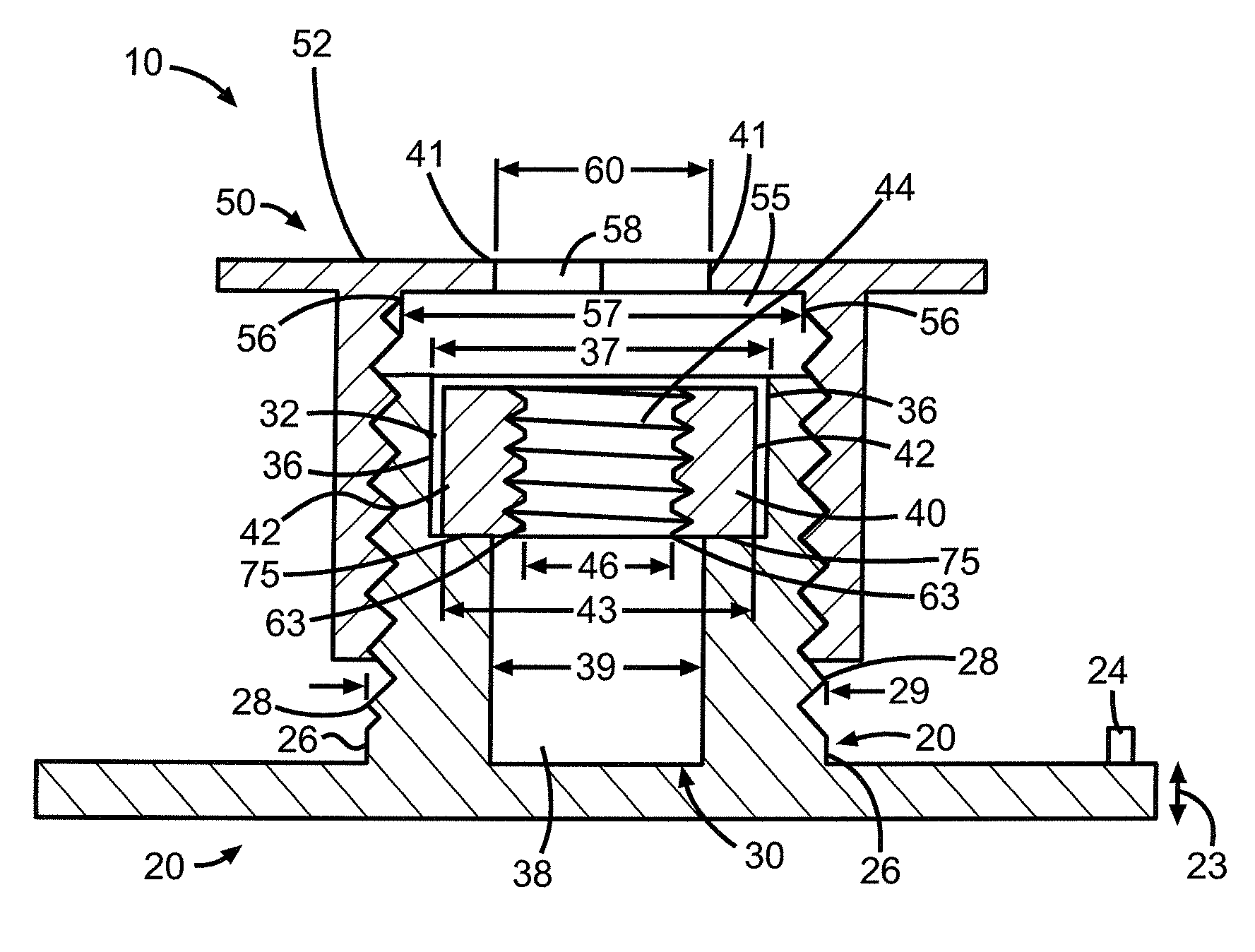
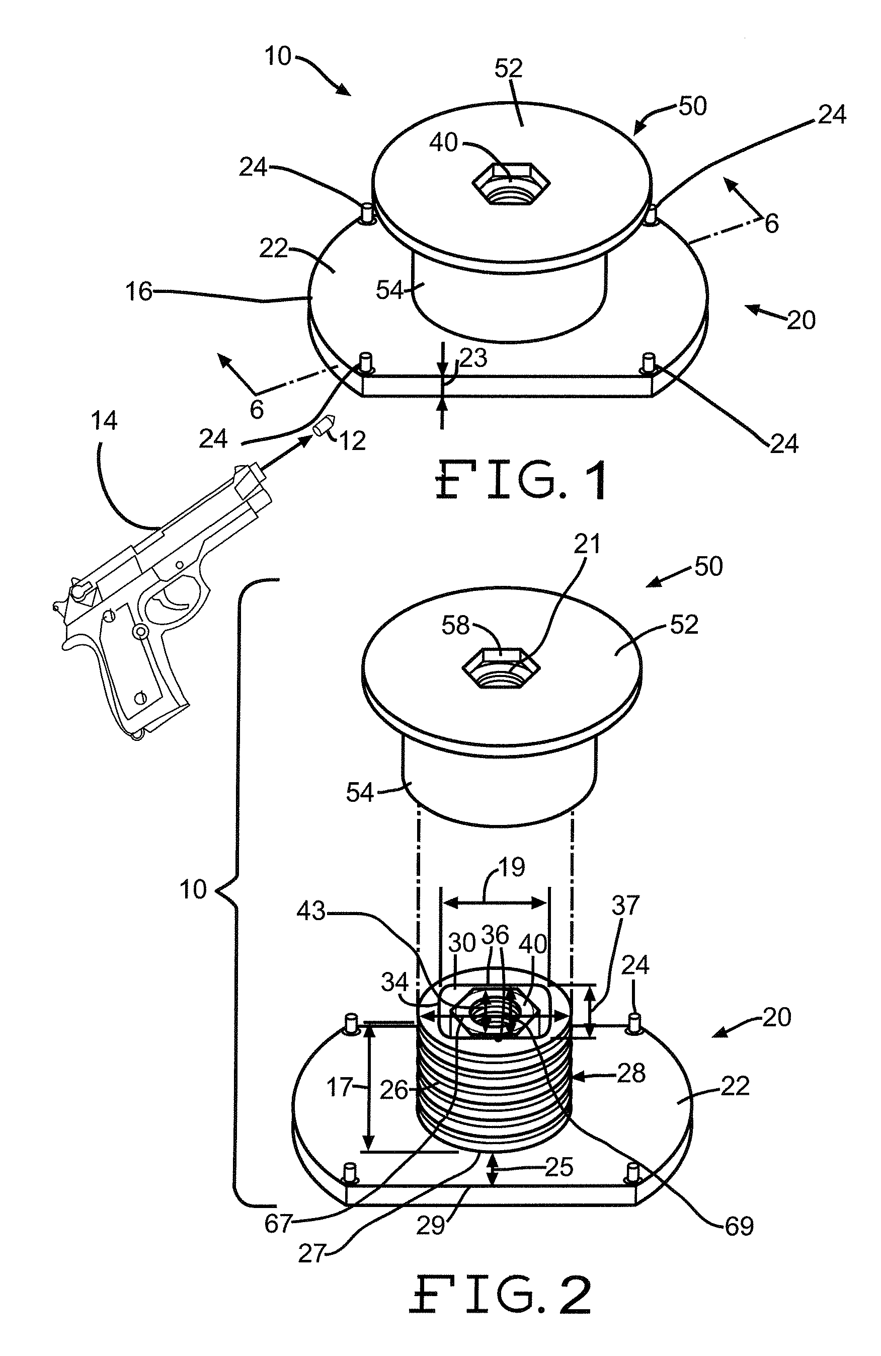
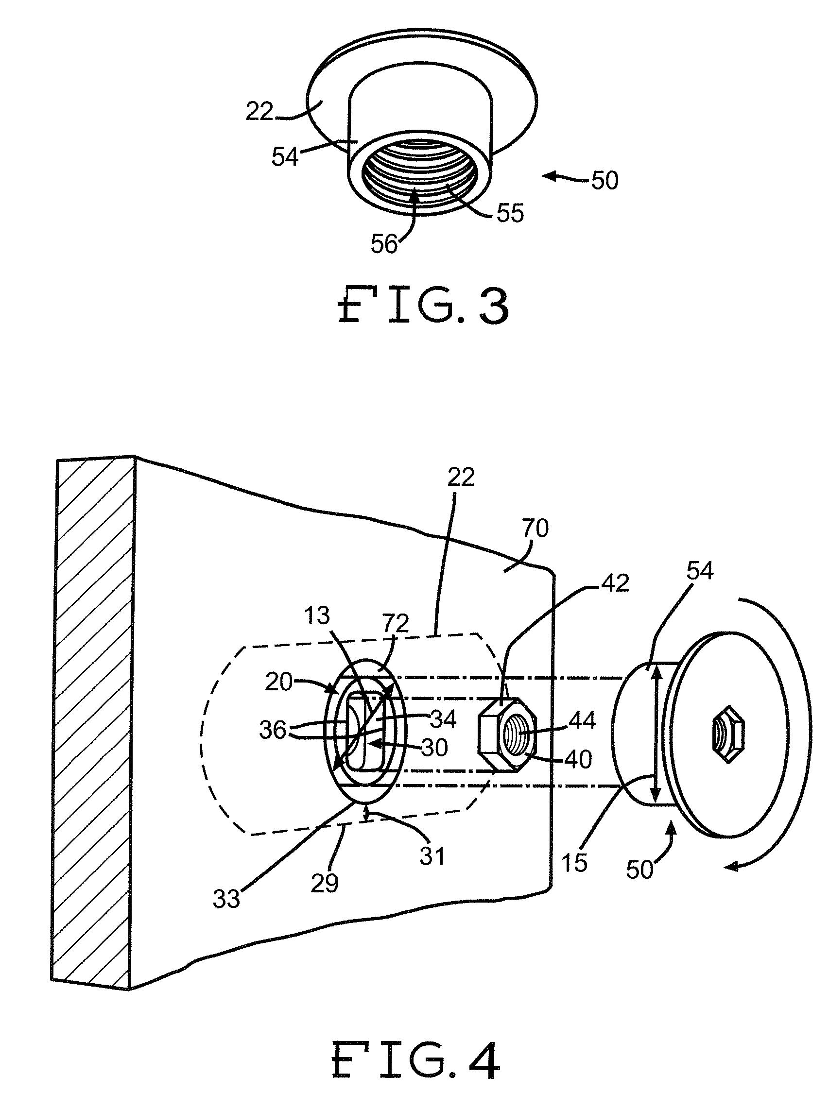
[0025]FIG. 1 shows a perspective view of a ballistic resistant through insert 10 in an assembled position, with the dashed line 6-6 showing the line along which the cross-sectional view shown in FIG. 6 is taken. The ballistic resistant through insert 10 may be adapted to stop a ballistic projectile 12. For purposes of this disclosure, a ballistic projectile 12 is defined as at least one of a bullet, a ballistic fragment, and a particle fragment. The ballistic resistant through insert 10 may comprise a stud 20, a floating nut 40, and a cap 50. The stud 20 and / or cap 50 may be made of a ballistic resistant material for stopping the ballistic projectile...


PUM


Abstract

A ballistic resistant through insert with floating capability for stopping a ballistic projectile, comprising at least one of a bullet, a ballistic fragment, and a particle fragment, may comprise a stud, a floating nut, and a cap. The stud may have a flat base portion and a cylindrical stud portion mounted thereon. The cylindrical stud portion may comprise a stud cylinder aperture. The floating nut may be located inside the stud cylinder aperture such that the floating nut floats within the stud cylinder aperture. The cap may have a flat cap portion and a cylindrical cap portion mounted thereon. The cylindrical cap portion may mate with the cylindrical stud portion. The stud may be made of a material for stopping a ballistic projectile. The flat base portion of the stud may have a minimum thickness for stopping a ballistic projectile.

Description

RELATED APPLICATIONS[0001]This application is a continuation-in-part of U.S. patent application Ser. No. 11 / 475,296, filed on Jun. 26, 2006, which is hereby incorporated by reference.FIELD OF THE DISCLOSURE[0002]The field of the disclosure relates to ballistic resistant through inserts with floating capabilities for stopping a ballistic projectile comprising at least one of a bullet, a ballistic fragment, and / or a particle fragment occurring due to the detonation of an explosive device.BACKGROUND OF THE DISCLOSURE[0003]It is often necessary to secure an object, such as a piece of furniture or equipment, to a panel. The panel may comprise a portion of a vehicle such as an aircraft. Some conventional apparatus and / or methods for installing an object to a panel may utilize one or more through inserts or blind inserts. The insert may be installed into the panel, and a fastener may be driven through a hole in the object and into the insert. However, conventional through inserts may not p...

Claims


Application Information

Patent Timeline
Patent Type & Authority Patents(United States)
IPC IPC(8): F16B37/04
CPCF16B5/025F16B37/044Y10T29/49947F16B37/14F16B37/122
Inventor KUNDA, JAMES J.
Owner THE BOEING CO
Why Eureka
Try Eureka