Undersize-hole oil pipe plugging device

A tubing plug, too small technology, applied in wellbore/well components, earthwork drilling, sealing/isolation, etc., can solve the problems of reliable clogging of tubing, high cost, not easy to clog, etc., to protect the environment And the effect of safe production, high safety in use, and high reliability of clogging

Active Publication Date: 2010-12-29
牡丹江金恒石油机械科技有限公司
View PDF7 Cites 21 Cited by
  • Summary
  • Abstract
  • Description
  • Claims
  • Application Information

AI Technical Summary

Problems solved by technology

[0003] 1. The method of plugging the tubing plug, but the outer diameter of the plugging part of the tubing plug and the inner diameter of the tubing should have an interference fit, and the tubing plug can only reach the inner diameter of the uppermost stage of the multi-stage water distributor in the pipe string The hole in the middle is smaller than the inner hole of the oil pipe, and the plugging device cannot pass through the small hole of the water distributor, that is to say, most of the tubing string below the uppermost water distributor cannot be blocked
[0004] 2. Directly lower the tool to block the small hole of the water distributor, but due to the complicated specifications and models of the water distributor, and the long-term corrosion of the sealing part of the underground water distributor, the plugging effect is not good
[0005] 3. There is also a method of placing a tool at the lower part of the pipe string first, and then injecting coagulant into the pipe string. However, this method has a long construction period, complicated operations, high cost, and poor reliability, and is not suitable for use.
[0006]Due to the high downhole pressure, it is not easy to reliably plug the tubing, and it is even more difficult to solve the plugging of the small hole of the downhole string tool such as the water distributor located below it. The oil pipe with a large inner diameter in the position, the plug is not easy to pass through the small hole and not easy to block the oil pipe, which is still an unsolvable technical problem

Method used


Image

  • Undersize-hole oil pipe plugging device
  • Undersize-hole oil pipe plugging device

Examples


Embodiment Construction

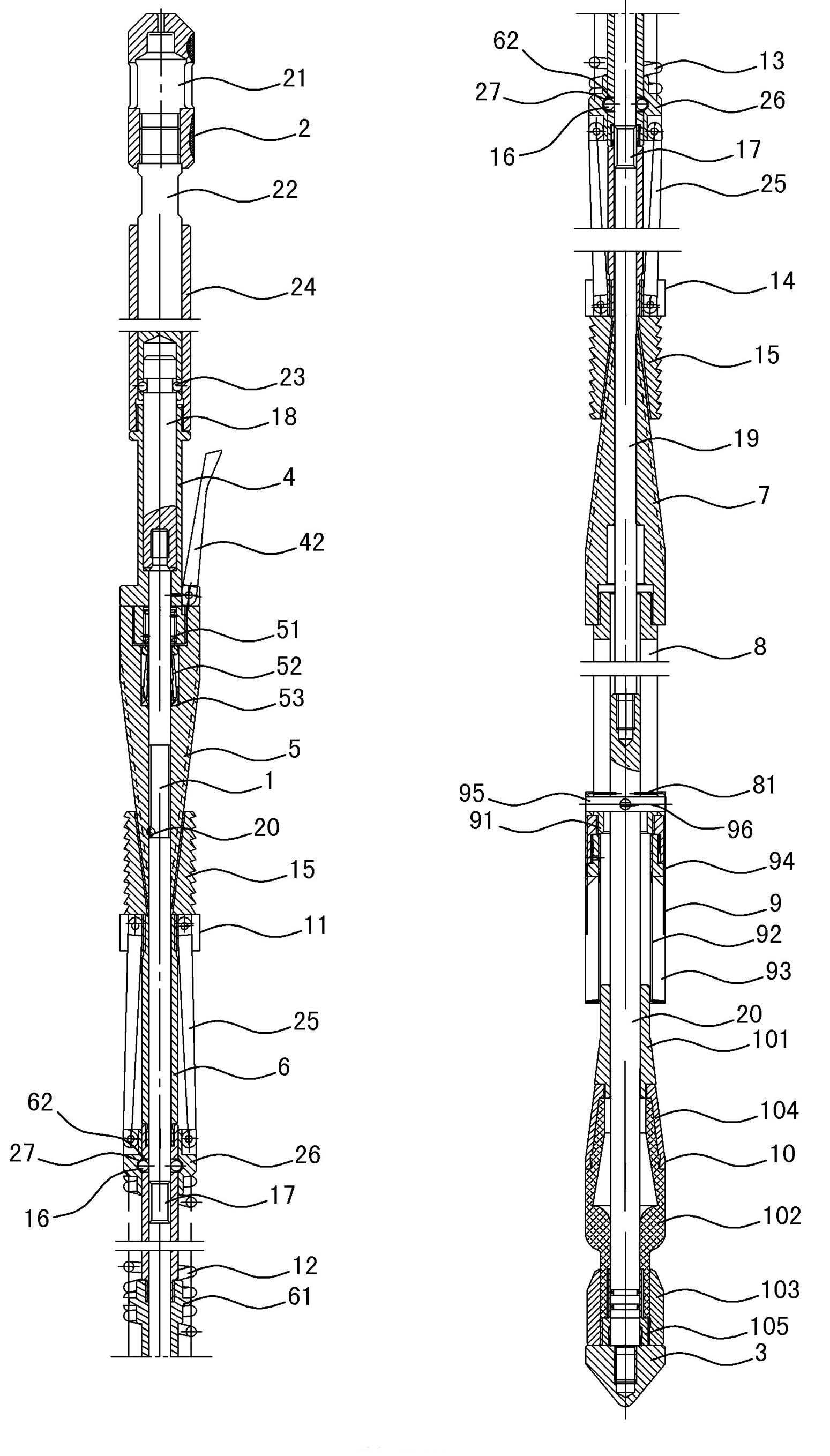
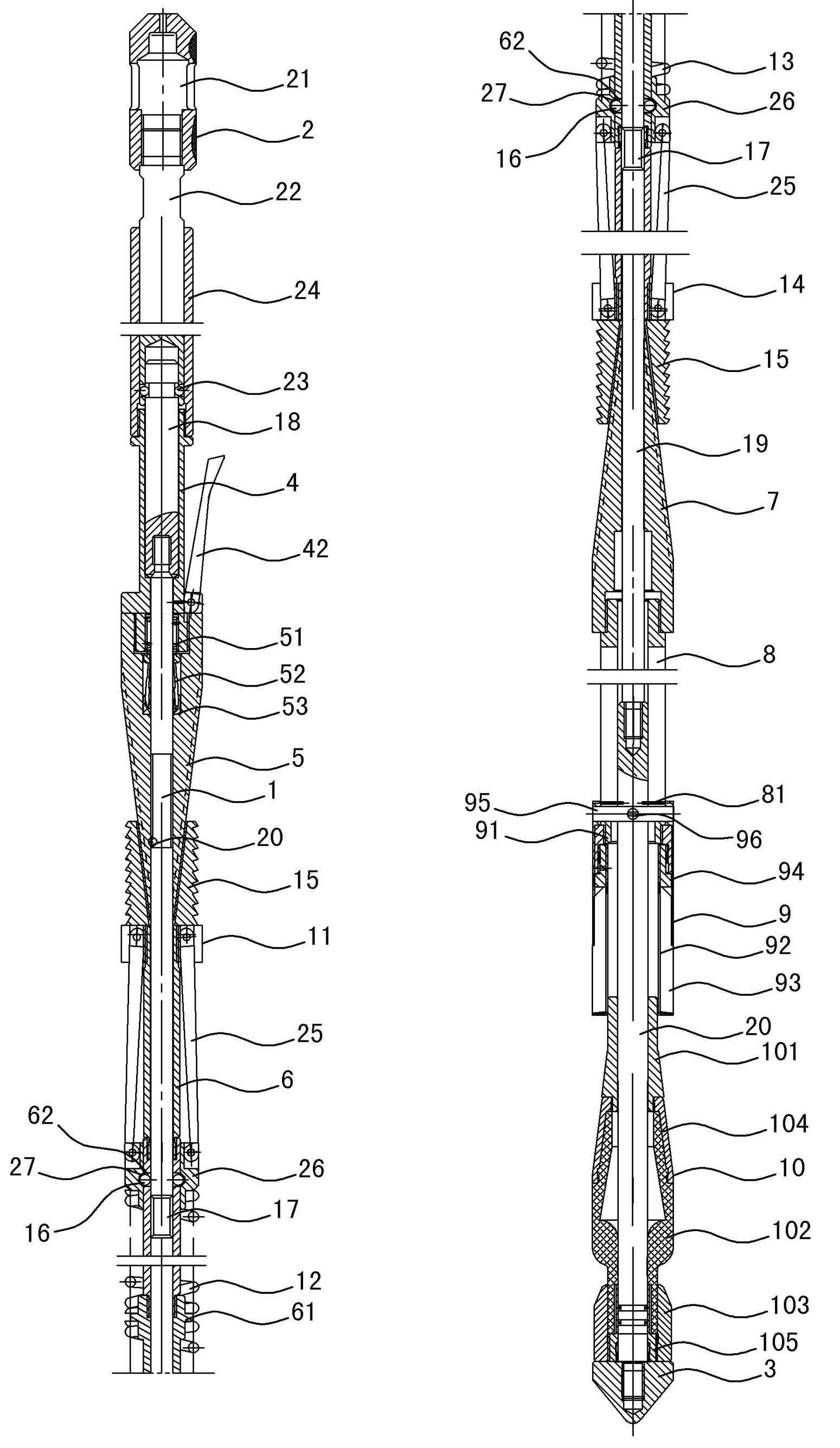
[0015] As shown in the figure, it includes a core rod 1. The upper end of the core rod 1 is connected with the feeder body 2, and the lower end is connected with the guide head 3. The upper end of the core rod 1 is connected with the head feeder body 2 and the guide head 3 from top to bottom. The set includes claw assembly 4, upper slip guide cone sleeve 5, middle connecting sleeve 6, lower slip guide cone sleeve 7, lower connecting sleeve 8, sheath assembly 9 and plugging assembly 10, upper slip guide cone Sleeve 5, middle connecting sleeve 6, lower slip guide tapered sleeve 7, lower connecting sleeve 8 and sheath assembly 9 are fixedly connected from top to bottom in sequence, middle connecting sleeve 6 and core rod 1 are guided by upper slips The upper slip assembly 11, the upper compression spring 12, the lower compression spring 13 and the lower slip assembly 14 are arranged sequentially from top to bottom between the taper sleeve 5 and the lower slip guide taper sleeve 7,...


PUM


Abstract

The invention relates to petroleum machinery, particularly to an oil pipe plugging device for plugging the inner hole of an oil pipe positioned below underground small-hole equipment, which comprises a core bar (1), wherein a clamping claw assembly (4), an upper slip guide taper sleeve (5), a middle connecting sleeve (6), a lower slip guide taper sleeve (7), a lower connecting sleeve (8), a jacket assembly (9) and a plug assembly (10) are sleeved on the core bar (1); and an upper slip assembly (11), an upper pressure spring (12), a lower pressure spring (13) and a lower slip assembly (14) are sleeved on the middle connecting sleeve (6). The oil pipe plugging device can be used for plugging a large-inside-diameter oil pipe positioned below thereof through the small hole of underground pipe column tools, such as a water distributor and the like, has the advantages of firm fixation in the oil pipe and high plugging reliability, can also be used for reliably plugging the underground oil pipe to prevent blowout from occurring, and ensures the normal water-well major repair operation, thereby playing roles of environmental protection and safe production, being high in use safety and more convenient to use and more beneficial to the safety of oilfield production.

Description

technical field [0001] The invention relates to petroleum machinery, in particular to an oil pipe plug used for blocking the inner hole of the oil pipe under the small hole equipment in the well. Background technique [0002] When repairing water wells during the implementation of modern oil production projects, it is necessary to lift the water injection pipe string together with the water distributor used for water injection out of the ground for maintenance and renewal. When the pipe string is lifted out of the ground, the formation high pressure formed by long-term water injection is the formation energy. There will be losses. After the maintenance is completed, it will take at least 60 days of high-intensity water injection to meet the needs of production to restore the formation pressure. At the same time as the loss of formation energy, it has a great impact on the production of surrounding oil wells, and during the maintenance process, a large amount of formation wat...

Claims


Application Information

Patent Timeline
Patent Type & Authority Applications(China)
IPC IPC(8): E21B33/127
Inventor 马中原
Owner 牡丹江金恒石油机械科技有限公司
Why Eureka
Try Eureka