Method for measuring flow of conductive fluid in non-full pipe by using electromagnetic flow meter

A technology of electromagnetic flowmeter and conductive fluid, which is applied in the application of electromagnetic flowmeter to detect fluid flow, volume/mass flow generated by electromagnetic effects, etc., which can solve the problems of measurement accuracy and achieve the effect of ensuring accuracy and overcoming measurement errors

Inactive Publication Date: 2010-12-29
ZHEJIANG UNIV
View PDF0 Cites 19 Cited by
  • Summary
  • Abstract
  • Description
  • Claims
  • Application Information

AI Technical Summary

Problems solved by technology

[0004] For the case where the single conductive fluid remains unchanged, that is, when the conductivity of the fluid remains unchanged, capacitive and double-excitation typ...

Method used


Image

  • Method for measuring flow of conductive fluid in non-full pipe by using electromagnetic flow meter
  • Method for measuring flow of conductive fluid in non-full pipe by using electromagnetic flow meter
  • Method for measuring flow of conductive fluid in non-full pipe by using electromagnetic flow meter

Examples


Embodiment Construction

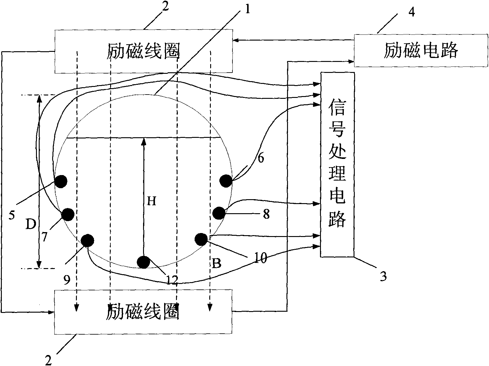
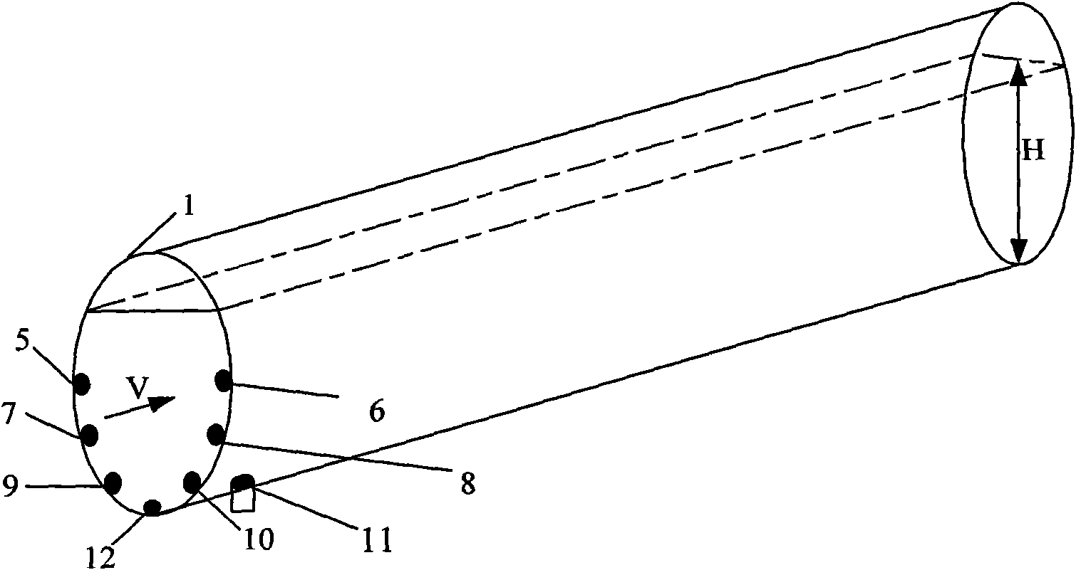
[0014] A preferred embodiment of the present invention is as follows: see figure 1 and figure 2 .

[0015] The method for measuring the flow of a conductive fluid in a partially filled pipe with an electromagnetic flowmeter includes the following steps:

[0016] 1) Connect the partially filled electromagnetic flowmeter to the fluid pipeline to be measured. The measuring tube 1 of the partially filled electromagnetic flowmeter is provided with an excitation coil 2 up and down. The excitation coil 2 is connected to the excitation circuit 4, and the inner wall of the pipeline is distributed There are three pairs of measuring electrodes, each pair of measuring electrodes is input into the signal processing circuit 3 in the form of a differential signal, and the three pairs of measuring electrodes are respectively connected to the signal processing circuit, and the ground electrode 12 at the bottom of the measuring tube 1 communicates with the excitation circuit 4 and the signal ...


PUM


Abstract

The invention discloses a method for measuring flow of conductive fluid in a non-full pipe by using an electromagnetic flow meter. The adopted flow meter is provided with at least three pairs of measuring electrodes, a grounding electrode, a coil structure for generating a magnetic field and a pressure sensor; a plurality of pairs of electrodes on the inner wall of the measured pipe ensure that each pair of electrodes is contacted with the fluid under different fluid levels H; and the measuring electrode pair is reasonably selected according to the different fluid levels so as to ensure the measurement accuracy. The measurement method is characterized in that: different pairs of electrodes are selected for measuring the flow rate under the different fluid levels, a fluid level signal H is obtained by using a pressure signal P of the pressure sensor so as to overcome measurement errors of the conductive fluids of different categories due to different conductivities and dielectric constants, the equivalent sectional area S of the fluid in the non-full pipe is calculated through the fluid level signal, the signal E of an induced electromotive force measured by the flow sensor is converted into a flow rate signal V, and the corresponding flow Q of the fluid in the non-full pipe can be obtained by integrating the equivalent sectional area S and the flow rate signal.

Description

technical field [0001] The invention relates to a method for measuring the flow of a conductive fluid in a partially filled pipe with an electromagnetic flowmeter. Background technique [0002] Ordinary electromagnetic flowmeters use a sensor with a constant cross-sectional area to measure the average flow velocity to obtain the flow rate. The cross-sectional area of ​​the fluid in the partially filled pipe changes, and the flow measurement must not only measure the average flow velocity flowing through the sensor, but also measure the cross-sectional area of ​​the fluid flowing through the sensor. That is to say, the flow measurement of the partially filled electromagnetic flowmeter requires at least two variables of flow velocity V and liquid level H. [0003] The measurement methods of the partial pipe electromagnetic flowmeter mainly include the method of using a large-area electrode sensor with a curved plate with the center of the pipe biased towards the bottom, the l...

Claims


Application Information

Patent Timeline
IPC IPC(8): G01F1/58
Inventor 周洪亮饶蕾张宏建
Owner ZHEJIANG UNIV
Why Eureka
Try Eureka