Converter transformer for inhibiting DC magnetic biasing

A converter transformer and DC bias technology, which is applied in the field of transformer manufacturing, can solve problems such as transformer no-load loss increase, power grid collapse, and vibration aggravation, and achieve the goal of reducing the degree of DC bias, reducing the impact and harm, and reducing vibration aggravation Effect

Active Publication Date: 2010-12-29
TBEA SHENYANG TRANSFORMER GRP CO LTD
View PDF0 Cites 8 Cited by
  • Summary
  • Abstract
  • Description
  • Claims
  • Application Information

AI Technical Summary

Problems solved by technology

[0004] Due to the half-wave saturation of the iron core, a large number of supersaturated flux linkages are closed outside the iron core, and the excitation current is severely distorted. The transformer itself will experience increased no-load loss, increased vibration, and increased noise. It will also cause transformer cores, metal structural parts, A series of hazards such as local overheating of the fuel tank, and even damage to the insulation, which will endanger the power system in severe cases and even cause the collapse of the power grid

Method used


Image

  • Converter transformer for inhibiting DC magnetic biasing
  • Converter transformer for inhibiting DC magnetic biasing
  • Converter transformer for inhibiting DC magnetic biasing

Examples


Embodiment 1

[0028] The method of the present invention is applied to a core-type transformer with side columns in the iron core, and is mainly reflected in increasing the joint width of the transformer iron core laminations, specifically:

[0029] Calculate the width and height of each level of lamination according to the reserved lamination joint width, core section, column spacing and window height;

[0030] Cut the laminations according to the lamination width and height calculated above;

[0031] Laminations are stacked two by one in the order of each level, and placed alternately on the core frame by level;

[0032] After all the laminations are stacked, fasten the laminations at all levels.

[0033] The seam width is not less than the tolerance, and is not greater than the seam center distance between adjacent two-stage laminations.

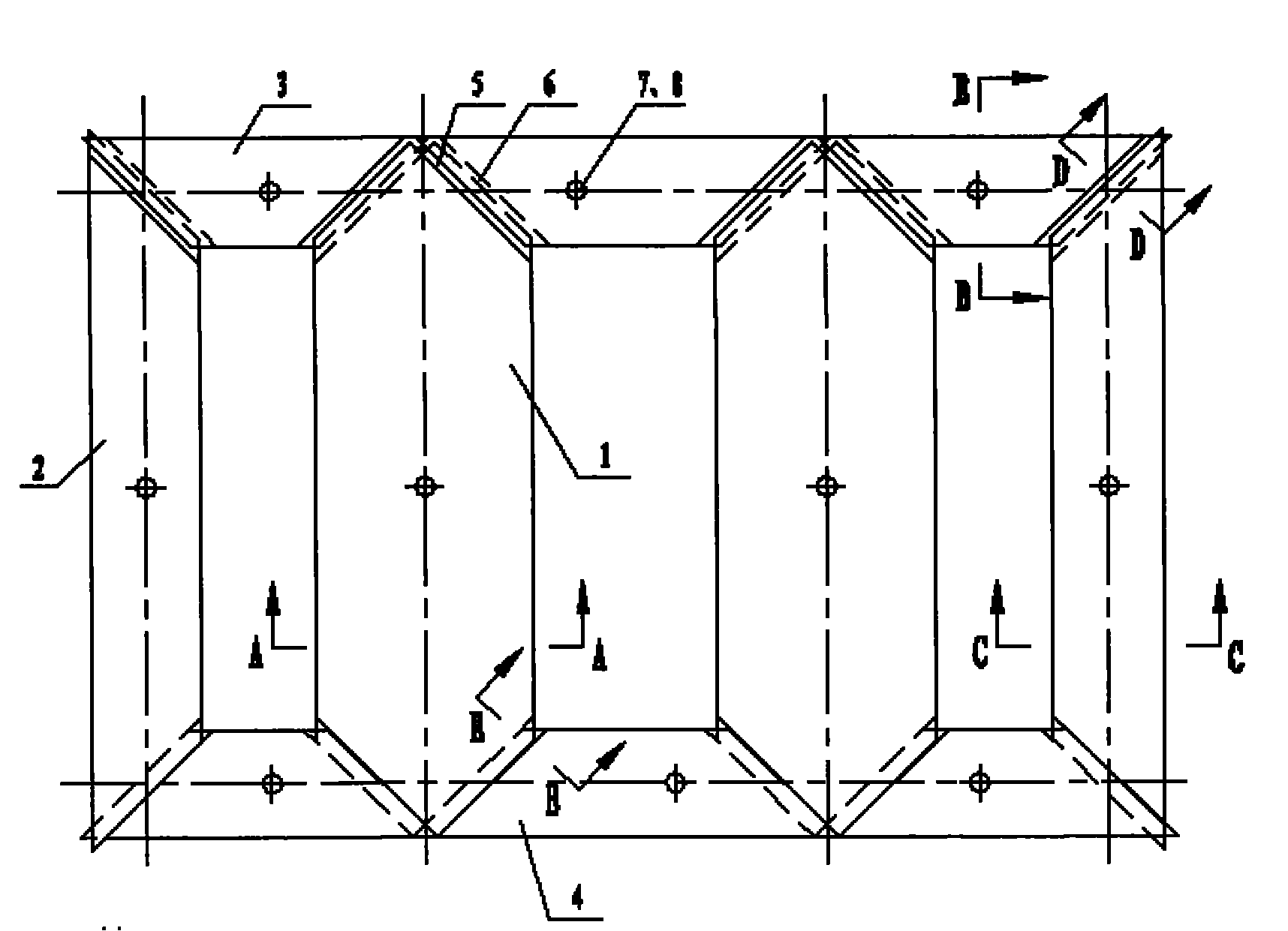
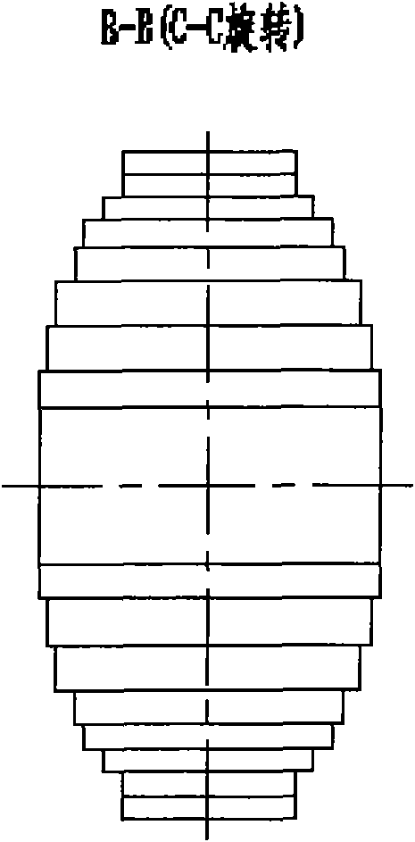
[0034] Such as Figure 2A-2E As shown, the iron core in this embodiment is a single-phase four-leg, including two main legs 1 , two side legs 2 , t...

Embodiment 2

[0041] Such as Figure 3A-3E As shown, the difference from Example 1 is that the iron core is a single-phase three-column, including one main column 1, two side columns 2, two upper yokes 3, two lower yokes 4, and the number of joints is 6 , all by increasing the width. The core laminations are still stacked in two, the first-level joints 5 and the second-level joints 6 are alternately placed, and the fastening of the laminations at all levels is still in the form of a combination of positioning holes 7 and through-core screws 8 .

[0042] According to the different technological requirements of various converter transformers, the laminations at all levels can be alternately placed with 1-6 joints respectively, and the laminations at all levels can also be fastened by adhesive bonding or strapping.


PUM


Abstract

The invention relates to a method for realizing a converter transformer for inhibiting DC magnetic biasing. In the method, joint widths among core laminations of the transformer are increased, and the method specifically comprises the following steps of: calculating the widths and heights of the laminations of each level according to the preserved joint width between every two laminations, the section of a core, the width between every two columns and the height of a window; cutting the laminations according to the calculated widths and heights of the laminations; laminating the laminations in a way of laminating every two laminations according to the sequence of the levels, and alternately arranging the laminations on a core frame according to the levels; and tightening the laminations of each level after all the laminations are laminated. The method has the advantages of effectively reducing the damage of DC magnetic biasing current to the transformer and further reducing the influence and damage of the transformer influenced by the DC magnetic biasing current on / to a power system.

Description

technical field [0001] The invention relates to the technical field of transformer manufacturing, in particular to a converter transformer used for suppressing DC bias under various capacities. Background technique [0002] Due to factors such as DC transmission network and geomagnetic changes, the ground potential of the neutral point of the transformer rises, causing the DC bias current to enter the transformer coil through the neutral point, resulting in half-wave saturation of the transformer excitation current. [0003] In the absence of DC, the no-load current of the transformer winding works in the linear segment of the core magnetization curve Φ(t). At this time, the excitation current is basically a sinusoidal waveform or a symmetrical state approximately sinusoidal, such as figure 1 Shown by the solid line in (c). However, under the action of DC current bias, the no-load excitation current shifts on the core magnetization curve Φ(t), and the half-wave of it works ...

Claims


Application Information

Patent Timeline
IPC IPC(8): H01F27/26H01F27/24H01F41/02
Inventor 王健李桂苹孙勇马志凯
Owner TBEA SHENYANG TRANSFORMER GRP CO LTD
Why Eureka
Try Eureka