
Back plate and communication equipment

A technology for communication equipment and backplanes, which is applied to the structural parts of electrical equipment, electrical components, and devices for connecting/disconnecting parts, etc., which can solve the problems of limited capacity of service boards and the inability to increase the height of backplanes without limit.

Active Publication Date: 2010-12-29
HUAWEI TECH CO LTD
View PDF0 Cites 18 Cited by
  • Summary
  • Abstract
  • Description
  • Claims
  • Application Information

AI Technical Summary

Problems solved by technology

[0004] As the number of slots in the horizontal direction increases, the height of the backplane also increases accordingly. However, due to the constraints of PCB manufacturing capabilities, the height of the backplane cannot be increased without limit, which limits the capacity of the service board.

Method used


Image

  • Back plate and communication equipment
  • Back plate and communication equipment
  • Back plate and communication equipment

Examples


Embodiment 1

[0020] In order to expand the access capacity and switching capacity of communication equipment, the embodiment of the present invention provides a backplane.

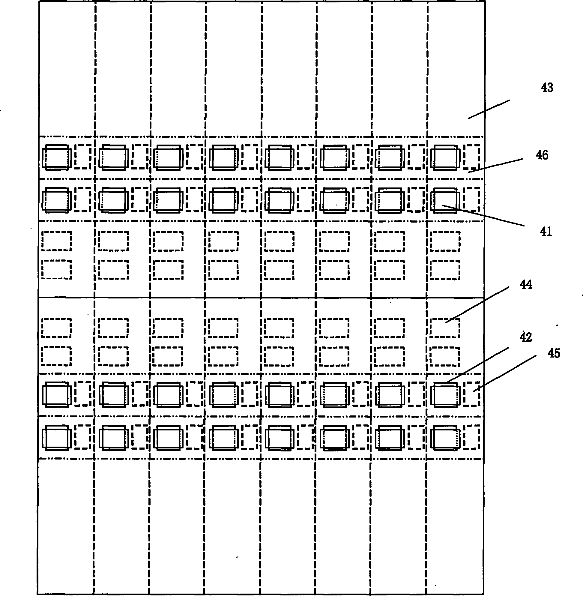
[0021] There is no structural difference between the two sides of the backplane. For the convenience of description, the backplane is divided into front and rear sides, as shown in figure 2 As shown, an upper subframe 12 and a lower subframe 13 are arranged on the front side of the backplane 11 , and an upper subframe 14 and a lower subframe 15 are arranged on the rear side of the backplane.

[0022] An insertion interface 16 is provided in each subrack, and the insertion interface 16 includes a first insertion interface for inserting a service daughter card and a second insertion interface for inserting a switching daughter card. The types of sockets set in the same subrack on the backplane can be the same, for example figure 2 As shown, the upper frame 12 and the lower frame 13 on the front side of the backplane c...

Embodiment 2

[0035] In order to expand the access capacity and switching capacity of communication equipment, the embodiment of the present invention provides a backplane.

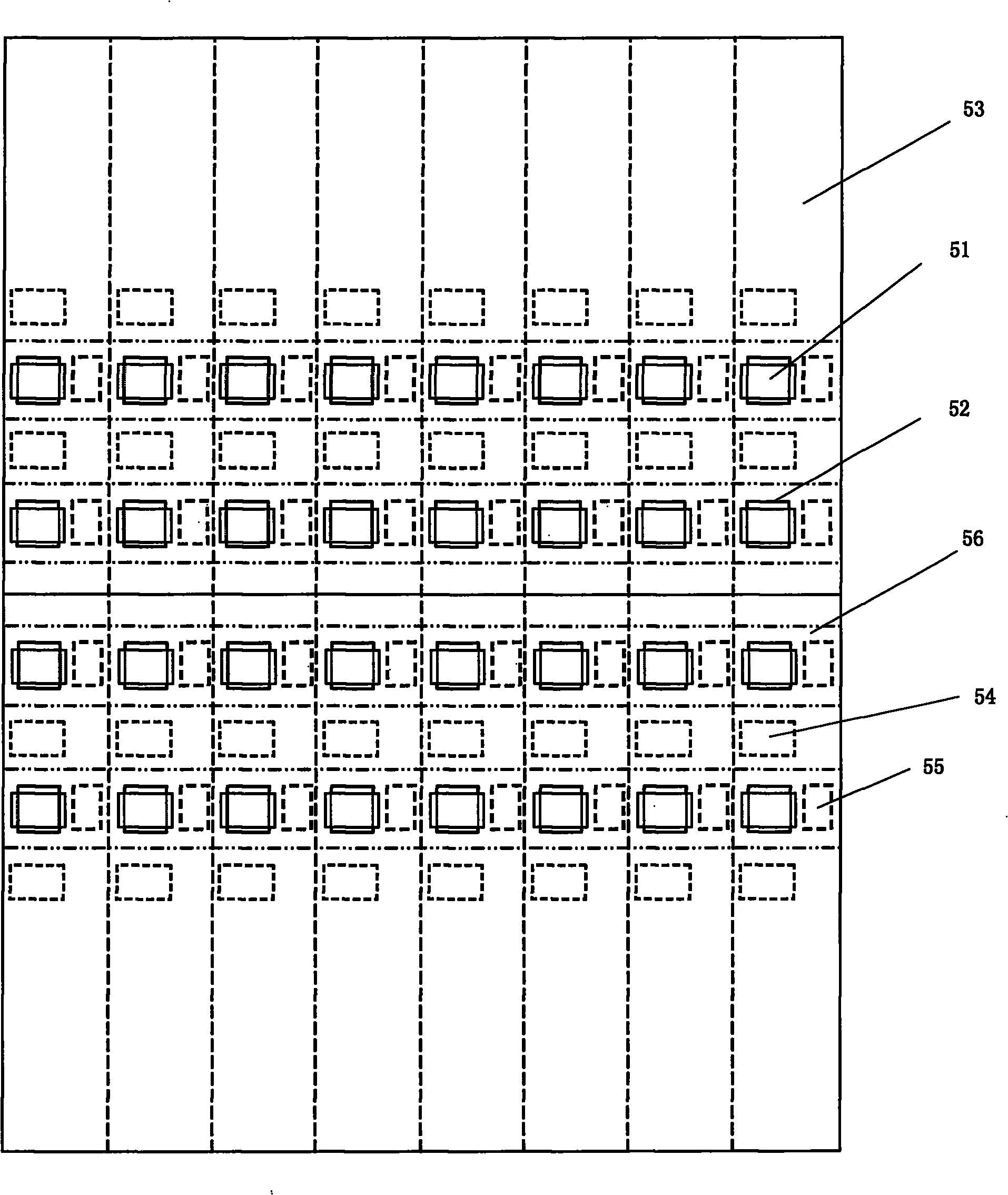
[0036] There is no structural difference between the two sides of the backplane. For the convenience of description, the backplane is divided into front and rear sides, as shown in Figure 4 As shown, an upper frame 22 , a middle frame 23 , and a lower frame 24 are arranged on the front side of the backplane 21 , and an upper frame 25 , middle frame 26 , and lower frame 27 are arranged on the rear side of the backplane.

[0037] The types of sockets provided in the same subframe of the backplane 21 can be the same. In the embodiment of the present invention, the first sockets 28 for the first type of daughter cards can be provided in the subframes on the front side of the backplane 21. A second socket 29 for plugging in a second type of daughter card is provided in the socket frame at the rear side of the backplane 21 ...


PUM


Abstract

The invention relates to a back plate and communication equipment. The back plate disclosed in the embodiment of the invention is provided with an insertion port respectively on the two sides, the insertion ports are used for connecting with at least two insertion frames, and the insertion ports comprise first insertion ports for inserting a first type of daughter cards and second insertion portsfor inserting a second type of daughter cards; the first insertion ports are provided with connectors, wherein the number of the connectors is not less than that of the second insertion ports; the second insertion ports are provided with connectors, wherein the number of the connectors is not less than that of the first insertion ports; the connectors on the first insertion ports are respectivelyconnected with one connector on each second insertion port, and the connectors on the second insertion ports are respectively connected with one connector on each first insertion port; and at least one first insertion port on one side of the back plate is crossed with at least one second insertion port on the other side of the back plate, orthogonal connectors are arranged on the back plate on the cross points of the first insertion ports and the second ports, and the first type of daughter cards inserted on the first insertion ports are connected with the second type of daughter cards inserted on the second insertion ports through the orthogonal connectors on the back plate.

Description

technical field [0001] The invention relates to the communication field, in particular to a backplane and communication equipment. Background technique [0002] The communication equipment includes three main components: the service board, the backplane and the switch board, and the signal communication between the service board and the switch board is realized through the backplane. Such as figure 1 The connection diagram of the orthogonal backplane system is shown. The service board and the backplane are connected through signal connectors. The physical interface density of the signal connector determines the access capacity of the service board; the switch board and the backplane are connected through signal Connector connection, the physical interface density of the signal connector determines the switching capacity of the switch board. Limited by the physical size of service boards and switch boards, the number of signal connector physical interfaces on service boards...

Claims


Application Information

Patent Timeline
IPC IPC(8): H04Q1/18H01R13/62
CPCH05K7/1445
Inventor 李铂
Owner HUAWEI TECH CO LTD
Learn More