Method for cutting brittle material substrate

A brittle material substrate and substrate technology, applied in stone processing equipment, glass cutting devices, fine working devices, etc., to achieve the effect of improving the quality of the end surface

Inactive Publication Date: 2011-01-05
MITSUBOSHI DIAMOND IND CO LTD
View PDF12 Cites 13 Cited by
  • Summary
  • Abstract
  • Description
  • Claims
  • Application Information

AI Technical Summary

Problems solved by technology

[0007] However, in the above-mentioned proposed technology, in order to accurately form the bending moment around the planned cutting line, it is necessary to correctly arrange the wedge at the position corresponding to the planned cutting line on the back surface of the substrate, and rigorous work is required.

Method used


Image

  • Method for cutting brittle material substrate
  • Method for cutting brittle material substrate
  • Method for cutting brittle material substrate

Examples


Embodiment Construction

[0024] Although the cutting method of the brittle material substrate of the present invention will be described in detail below, the present invention is not limited to these implementation forms.

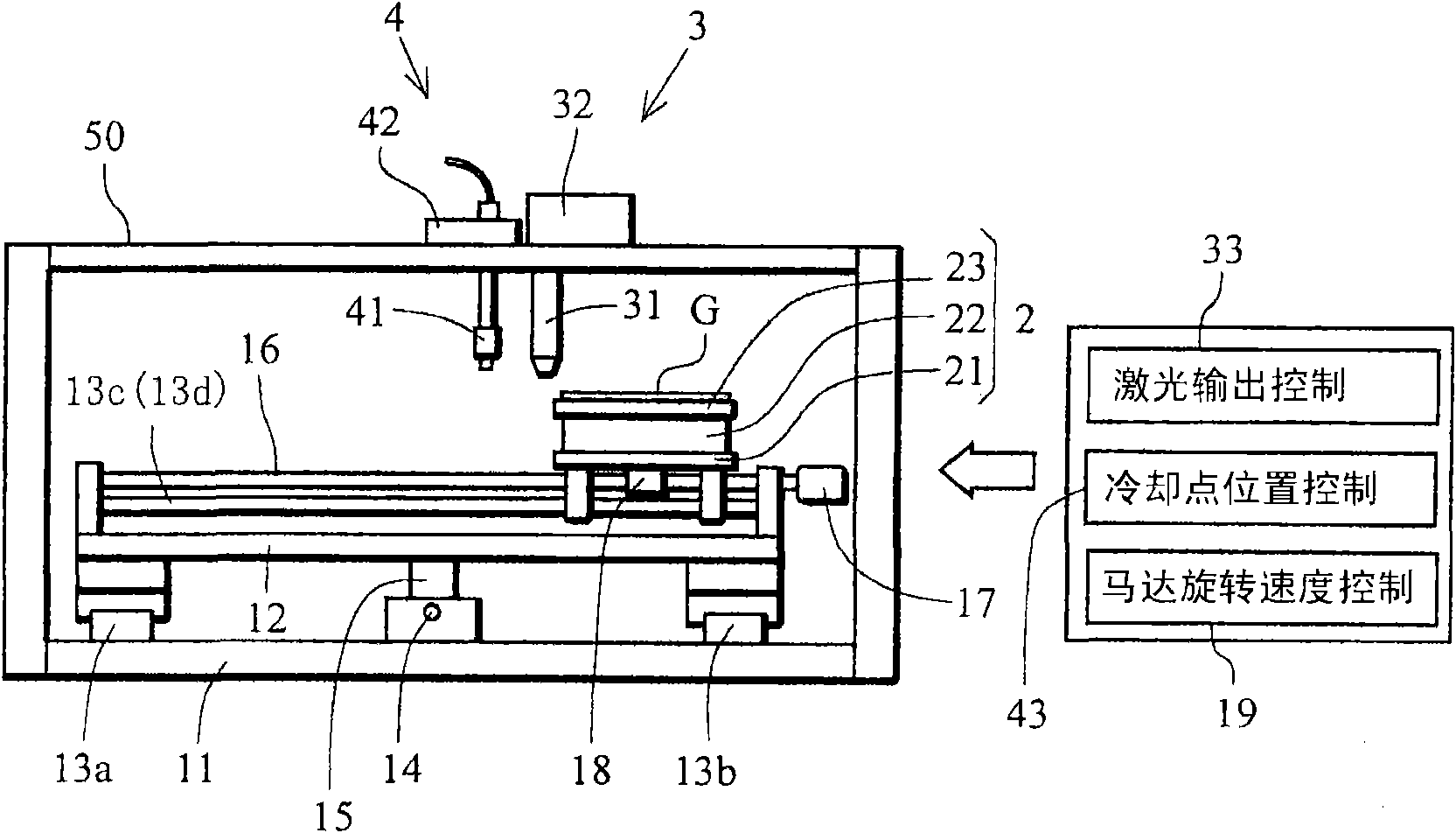
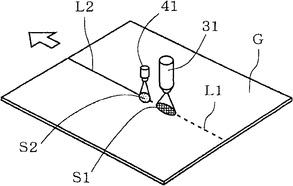
[0025] At figure 1 A schematic diagram showing an example of a cutting device capable of carrying out the cutting method of the present invention. exist figure 1 In the cutting device of the present invention, a pair of guide rails 13a, 13b are arranged in parallel at a predetermined distance on the horizontal platform 11 . Moreover, the slide table 12 which moves in the direction perpendicular to the paper surface on this pair of guide rails 13a, 13b is provided. A pillar 15 is suspended downward from the lower surface of the slide table 12 . A lead screw 14 arranged parallel to the guide rails 13a, 13b between the guide rails 13a, 13b is screwed to the support 15, and the lead screw 14 is rotated forward and reverse by a motor not shown, so that the slide table 12 moves alon...


PUM

PropertyMeasurementUnit
lengthaaaaaaaaaa

Abstract

In a method for cutting a brittle material substrate by laser, a terminal is used to make a vertical crevasse crack to a cutting destined line. The method includes: a step of forming an initial crevasse crack on a cutting beginning end of the cutting destined line on one surface of the brittle material substrate; and steps of moving and irradiating a laser beam from the initial crevasse crack along the cutting destined line, heating the substrate at a temperature less to a fusion temperature, then immediately cooling the substrate by a cooling medium so as to make the substrate to generate a thermal stress to make the initial crevasse crack to evolve along the cutting destined line, so as to form a vertical crevasse crack arriving the back face of the substrate. Furthermore, by means of changing one of the heating condition of the laser beam and the cooling condition of the cooling medium in the step of evolving the initial crevasse crack, the vertical crevasse crack will not arrive the back face of the substrate.

Description

technical field [0001] The present invention relates to a cutting method of a brittle material substrate, and more particularly relates to a cutting method of a brittle material substrate using a laser. Background technique [0002] Conventionally, as a cutting method for a brittle material substrate such as a glass substrate or a ceramic substrate, it is widely used to press a cutter wheel or the like on the surface of a brittle material substrate and rotate it simultaneously to form a crack in a direction approximately perpendicular to the surface of the brittle material substrate ( Hereinafter referred to as "vertical cracks"), and then apply a mechanical pressure to the substrate to cause the vertical cracks to progress in the thickness direction of the substrate to cut the substrate. [0003] However, generally, when a cutter wheel is used to form vertical cracks in a brittle material substrate, small fragments called cullets are generated, and the glass cullets may cau...

Claims


Application Information

Patent Timeline
Patent Type & Authority Applications(China)
IPC IPC(8): B23K26/00B23K26/42C03B33/09B28D5/00
CPCB23K26/389C03B33/033C03B33/082C03B33/091Y02P40/57
Inventor 清水政二山本幸司在间则文
Owner MITSUBOSHI DIAMOND IND CO LTD
Why Eureka
Try Eureka