Decoupled tri-rotation parallel mechanism

A three-rotation, parallel technology, applied in the direction of manipulators, program-controlled manipulators, metal processing machinery parts, etc., can solve the problems of low motion precision, inconvenient control, complex structure, etc., and achieve small moment of inertia, simple control, and motion decoupling Effect

Inactive Publication Date: 2011-08-17
SHANGHAI UNIV OF ENG SCI
View PDF7 Cites 0 Cited by
  • Summary
  • Abstract
  • Description
  • Claims
  • Application Information

AI Technical Summary

Problems solved by technology

[0005] The purpose of the present invention is to provide a decoupled three-rotation parallel mechanism to overcome the defects of complex structure, inconvenient control and low motion precision in the prior art

Method used


Image

  • Decoupled tri-rotation parallel mechanism
  • Decoupled tri-rotation parallel mechanism

Examples


Embodiment Construction

[0017] Below in conjunction with specific embodiment, further illustrate the present invention. The drawings show a preferred embodiment of the present invention, and the technical solution of the present invention is not limited to this embodiment.

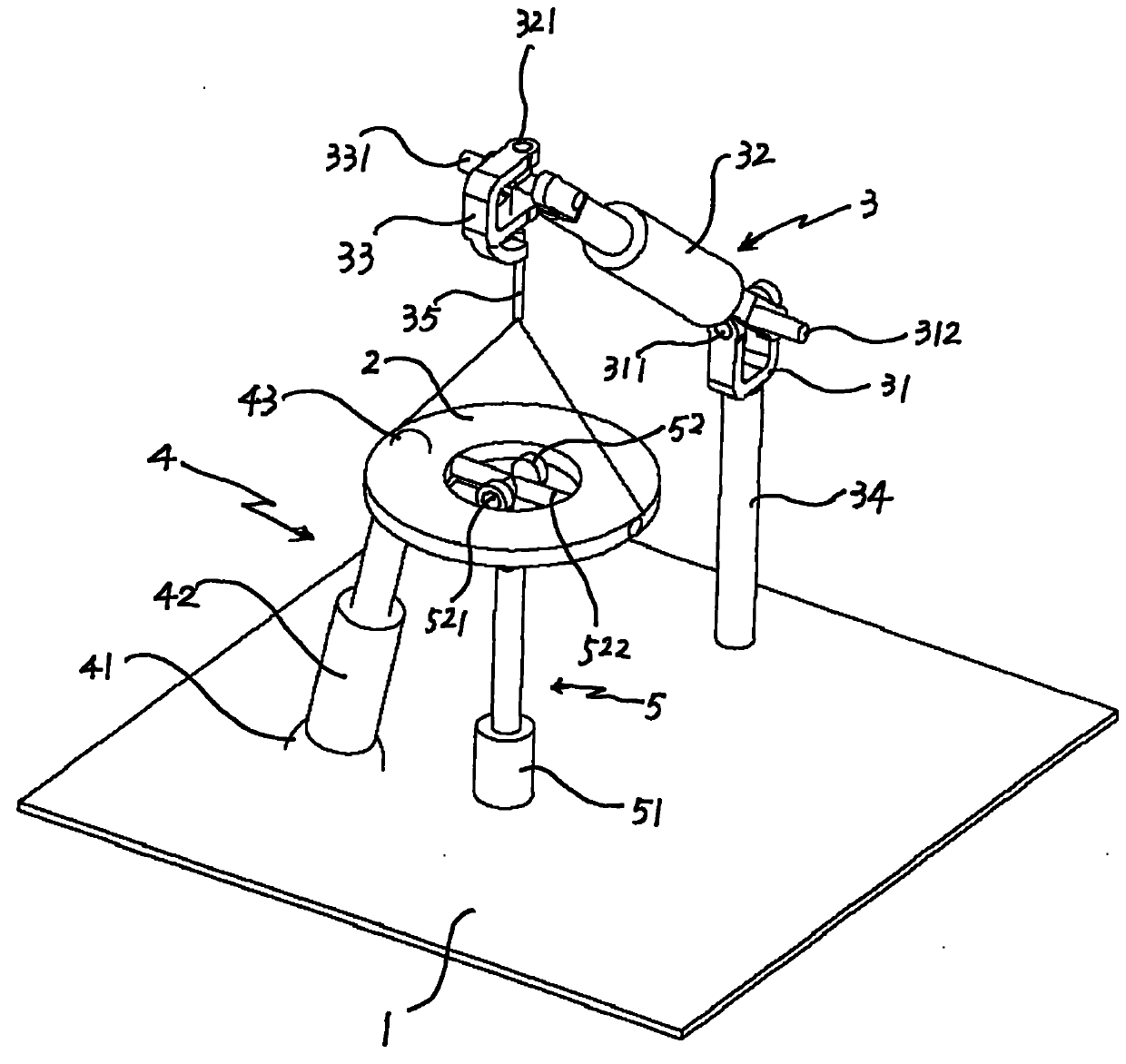
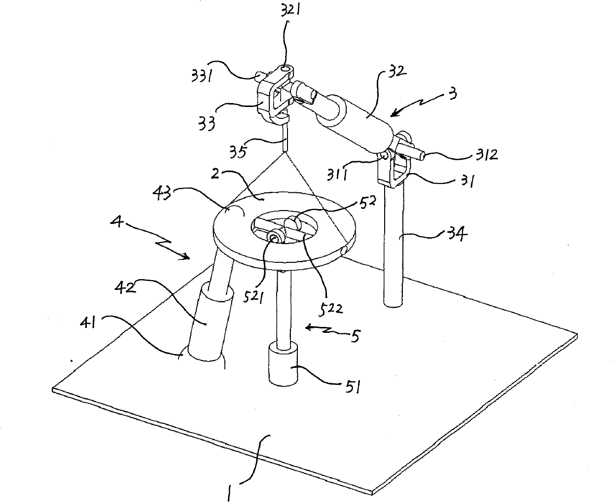
[0018] see figure 1 , the decoupled three-rotation parallel mechanism of the present invention consists of a frame 1, a moving platform 2, and a first kinematic branch chain 3 connected between the frame and the moving platform, a second kinematic branch chain 4 and a third kinematic branch chain 5 composition.

[0019] The first kinematic branch chain 3 comprises the first universal hinge 31, the first moving pair 32 and the second universal hinge 33 connected in sequence; the other end of the first universal hinge 31 is connected with the frame 1 through a connecting rod 34, and the second The other end of two universal hinges 33 is connected with moving platform 2 by connecting rod 35 .

[0020] The second kinematic branch ...


PUM


Abstract

The invention provides a decoupled tri-rotation parallel mechanism, which comprises a stand, a moving platform, a first moving branch chain, a second moving branch chain and a third moving branch chain, wherein the first moving branch chain, the second moving branch chain and the third moving branch chain are connected between the stand and the moving platform. The first moving branch chain comprises a first universal hinge, a first moving pair and a second universal hinge which are sequentially connected; the second moving branch chain comprises a first spherical hinge, a second moving pair and a second spherical hinge which are sequentially connected; and the third moving branch comprises a rotation pair and a third universal hinge which are sequentially connected. The invention has three decouple rotational degrees of freedom, and the rotational freedom degree of freedom only depends on the linear control of the moving pair of the moving branch chains, therefore, the implementationprinciple is very simple and the mechanism has quite good linear relation.

Description

technical field [0001] The invention relates to a machine tool and an industrial robot, in particular to a three-rotation parallel mechanism for decoupling a virtual-axis numerical control machine tool with a parallel structure and a parallel robot. Background technique [0002] Parallel mechanisms are widely used in heavy-duty simulation equipment, robots, CNC machine tools, sensors and micro-operation fields. However, the driving units of the parallel mechanism are coupled, that is, the movement of the overall output platform (moving platform) of the parallel mechanism in any direction is the synthesis of the movements of all driving units, and the movement of each driving unit is combined with the overall movement of the parallel mechanism ( That is, the relationship between input and output) is nonlinear. This characteristic leads to complex control of parallel mechanism, difficult calibration, and restricts the improvement of accuracy. Therefore, how to achieve decoup...

Claims


Application Information

Patent Timeline
Patent Type & Authority Patents(China)
IPC IPC(8): B25J9/08B23Q1/44
Inventor 张帆徐新成胡义刚朱建军刘燕宋芳
Owner SHANGHAI UNIV OF ENG SCI
Why Eureka
Try Eureka