Bearing insert to be inserted in inner hole part of plastic flow deflector shell of engineering plastic well pump

A technology of engineering plastics and guide shells, applied in the components, pump components, pumps and other directions of pumping devices for elastic fluids, can solve problems such as increased manufacturing costs, motor damage, inability to withstand radial forces, etc., and achieves low Production cost, effect of high bearing performance

Inactive Publication Date: 2011-01-05
JIANGSU UNIV
View PDF1 Cites 4 Cited by
  • Summary
  • Abstract
  • Description
  • Claims
  • Application Information

AI Technical Summary

Problems solved by technology

However, this kind of radial sliding bearing cannot bear the axial force of the impeller. When there are many impellers in the well pump, the sum of the axial forces of all the impellers may be too large to the extent that the thrust bearing in the supporting motor cannot bear, resulting in motor failure. damage
The invention patent with the application number 200910161415.6 "Deep Well Centrifugal Pump with Two Thrust Bearing Pairs for Each Stage Impeller" adopts the method that the axial force of each impeller is borne by the two thrust bearing pairs of each stage in the plastic well pump, It solves the problem of the axial force of the well pump impeller, but this invention ignores the problem of the radial force of the impeller. The stainless steel plate embedded in the plastic diversion shell can only bear the axial force but not the radial force, so every Adding 4 to 6 impellers requires an additional support for sliding bearings, such as figure 2 shown, which increases the manufacturing cost

Method used


Image

  • Bearing insert to be inserted in inner hole part of plastic flow deflector shell of engineering plastic well pump
  • Bearing insert to be inserted in inner hole part of plastic flow deflector shell of engineering plastic well pump
  • Bearing insert to be inserted in inner hole part of plastic flow deflector shell of engineering plastic well pump

Examples


Embodiment Construction

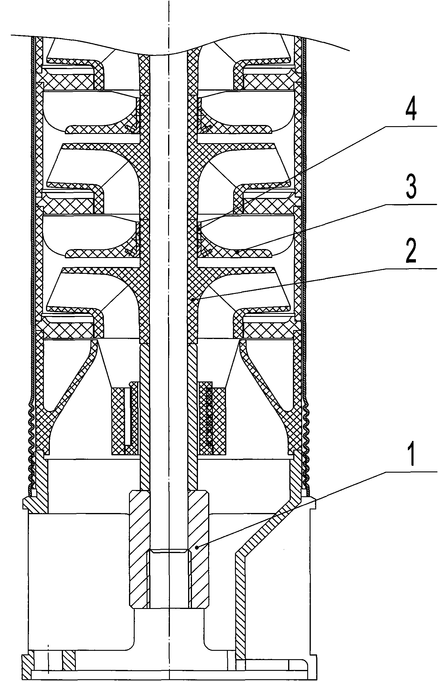
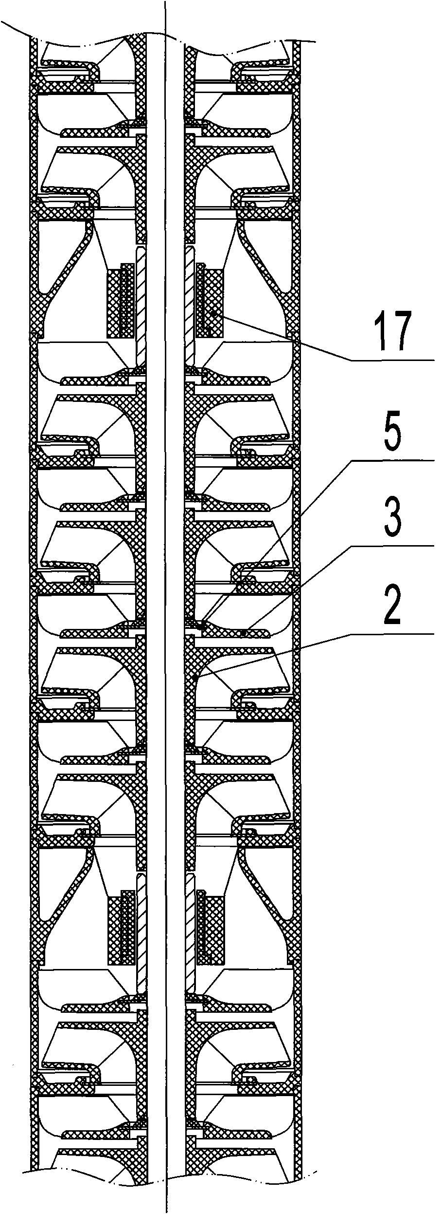
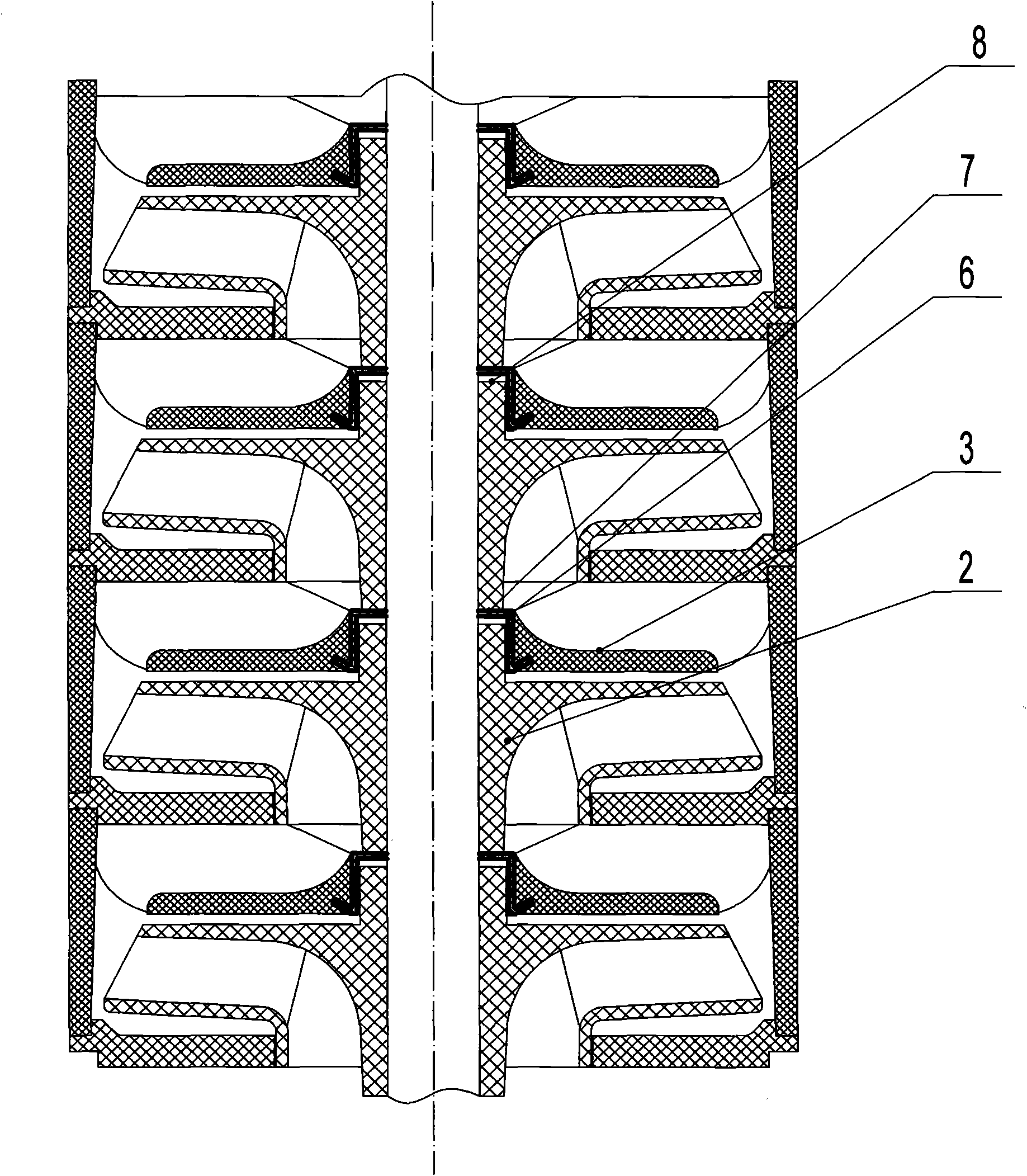
[0018] image 3 The illustrated embodiment is a part of a multistage well pump in which both the impeller 2 and the diversion casing 3 are made of engineering plastics. In the plastic diversion casing 3, a radial thrust bearing insert 6 is inlaid, and the whole of the insert Shaped like the shape of a top hat, such as Figure 5 As shown, its top 9 is a plane ring, its middle part 10 is a cylinder, and its lower part 12 is a uniformly distributed flange. After the plastic guide shell 3 is injected, the insert top 9 and the inner wall of the cylinder 10 are exposed outside, such as Figure 4 shown.

[0019] The insert has some through holes 11 evenly distributed on the wall of the middle cylinder, and some through holes 13 are also evenly distributed on the plate surface of the lower flange. These through holes are filled with plastic after the plastic diversion shell is injected, so that the bearing The insert is firmly integrated with the plastic diversion shell, such as ...


PUM


Abstract

The invention discloses a bearing insert to be inserted in the inner hole part of the plastic flow deflector shell of an engineering plastic well pump, which is formed by punching a stainless steel plate and is matched with an engineering plastic impeller hub to form a sliding radial bearing and a sliding thrust bearing for bearing the radial force and axial force of the impeller. The upper side of the top part of the insert and the lower end of the impeller hub on the upper side form a lower plain thrust bearing for bearing the downward axial force of the impeller; the downside of the top part of the insert and the upper end of the impeller hub on the down side form an upper plain thrust bearing for bearing the upward axial force applied when the well pump starts; and the inner wall of the cylinder of the insert and the external circle of the impeller hub form a radial sliding bearing for bearing the radial force of the impeller. As a bearing pair with high performance is made of stainless steel and the engineering plastic, the reliability of the engineering plastic multi-stage well pump is improved greatly. The shape of the bearing insert is very suitable to be formed by punching and is also very suitable to be connected with the plastic flow deflector shell into a whole firmly, so material and labor can both be saved.

Description

Technical field [0001] The invention relates to a bearing insert inlaid in the inner hole of the plastic guide shell of an engineering plastic well pump, especially used as a sliding bearing in an engineering plastic well pump that needs to overcome both the radial force and the axial force of the impeller. The insert used is embedded in the inner hole of the plastic diversion shell. Background technique [0002] As we all know, well pumps have impeller radial force and impeller axial force. When the impeller and guide casing of the well pump are made of engineering plastics, how to bear the impeller radial force and impeller axial force becomes an important issue that affects the service life. . In general, the axial force of the impeller is borne by the thrust bearing in the supporting motor, while the radial force of the impeller is borne by the plastic hub of the impeller and the plastic hole of the plastic guide shell directly paired to form a plastic bearing pair. Ho...

Claims


Application Information

Patent Timeline
Patent Type & Authority Applications(China)
IPC IPC(8): F04D29/046
Inventor 陆伟刚张德胜王洪亮周岭
Owner JIANGSU UNIV
Why Eureka
Try Eureka