Torsional vibration damper

Inactive Publication Date: 2008-10-23
ZF FRIEDRICHSHAFEN AG
View PDF5 Cites 2 Cited by
  • Summary
  • Abstract
  • Description
  • Claims
  • Application Information

AI Technical Summary

Benefits of technology

[0011]An object of the present invention is to provide a torsional vibration damper in which the forces acting on the damping element units do not produce any operating problems generated by axial forces.

Problems solved by technology

A problem with these types of torsional vibration dampers is that, during operation in rotational mode, not only the compressive forces acting in the circumferential direction but also centrifugal forces exert load on the damping element units.

Method used


Image

  • Torsional vibration damper
  • Torsional vibration damper
  • Torsional vibration damper

Examples


Embodiment Construction

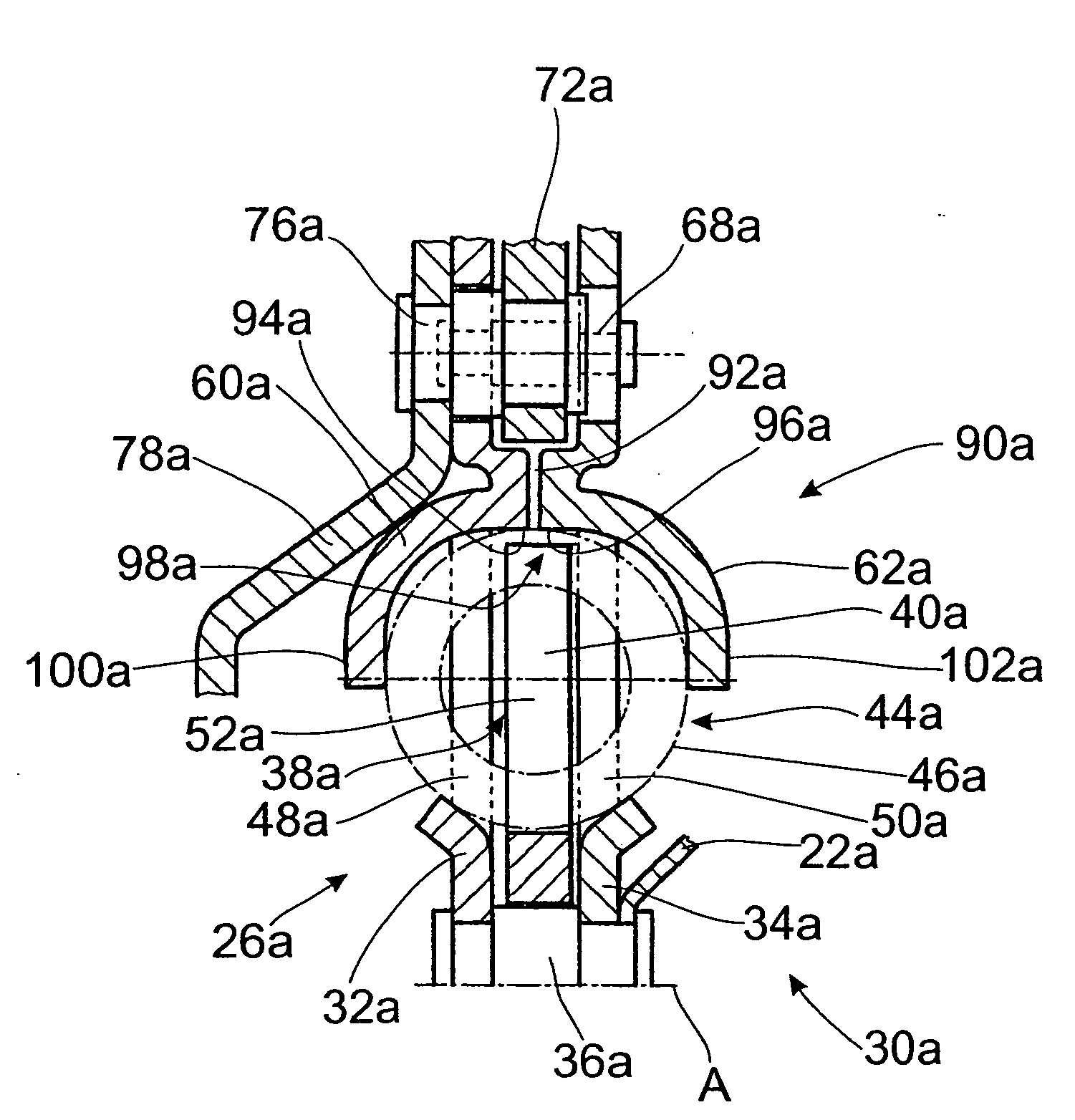
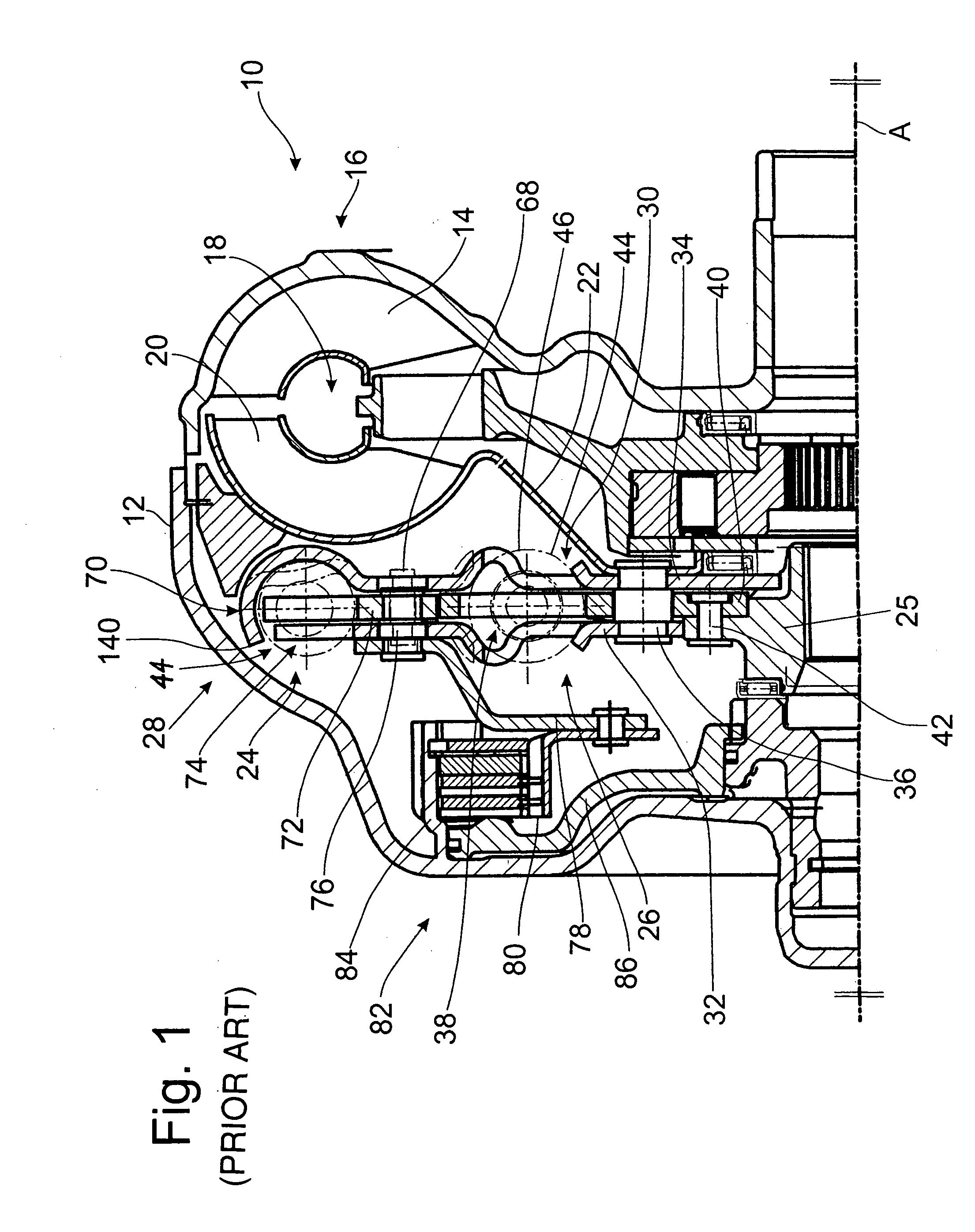
[0049]In the following, various embodiments of torsional vibration dampers designed according to the invention are described, which can be integrated, for example, into the torsional vibration damper arrangement 24 shown in FIG. 1 in conjunction with a hydrodynamic torque converter 10. Thus, in the following, the same reference numbers are used for the same assemblies, a suffix being added to characterize the specific embodiment in question. It should be pointed out, however, that the various torsional vibration dampers described below can also be provided in other types of systems such as dual-mass flywheels, clutch disks, etc.

[0050]FIG. 3 shows a torsional vibration damper 26a, in which, for example, the two cover disk elements 32a, 34a can provide the primary side 30a, whereas the central disk element 40a provides essentially the secondary side 38a.

[0051]The support sections 60a, 62a of the cover disk elements 32a, 34a located radially outside the damping element openings 48a, 5...


PUM


Abstract

A torsional vibration damper includes a primary side having a pair of axially spaced cover disk elements which are fixed to each other, and a central disk element axially between the cover disk elements, wherein each disk element has a like plurality of circumferentially arranged openings, and each opening has a pair of circumferential support areas. A like plurality of damping element units are arranged in respective sets of openings, and are supported against the circumferential support areas. A radial support surface supports each damping element unit in a radially outward direction, each radial support surface extending without curvature in the axial direction.

Description

BACKGROUND OF THE INVENTION[0001]1. Field of the Invention[0002]The present invention pertains to a torsional vibration damper having a primary side and a secondary side which can rotate around an axis of rotation with respect to the primary side against the action of a damping element arrangement, wherein one of the two sides includes two cover disk elements arranged a certain distance apart and permanently connected to each other, and the other one of the two sides includes a central disk element which engages axially between the cover disk elements. The damping element arrangement has a plurality of damping element units arranged in a row around the circumference, and damping element openings provided in the cover disk elements and in the central disk element to hold these damping element units. The damping element units are supported against the circumferential support areas forming the essentially circumferential boundaries or the damping element openings, a radial support arra...

Claims


Application Information

Patent Timeline
Patent Type & Authority Applications(United States)
IPC IPC(8): F16F15/139
CPCF16F15/1232F16H45/02F16H2045/0226
Inventor AMENT, NORBERTFELDHAUS, REINHARDWACK, ERWINPETERSEIM, MICHAELMARKOW, ALEXANDER
Owner ZF FRIEDRICHSHAFEN AG
Why Eureka
Try Eureka