
Sensor structure of microwave oven

A sensor and microwave oven technology, applied in the field of microwave ovens, can solve problems such as malfunction of microwave ovens, reduction of infrared sensitivity, and influence of sensor accuracy.

Inactive Publication Date: 2011-01-12
LG ELECTRONICS (TIANJIN) APPLIANCES CO LTD
View PDF7 Cites 6 Cited by
  • Summary
  • Abstract
  • Description
  • Claims
  • Application Information

AI Technical Summary

Problems solved by technology

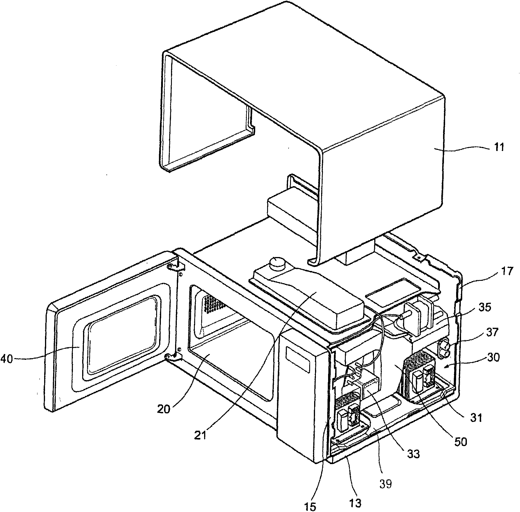
[0009] In the prior art, the sensor shell is directly fixed on the upper edge of the microwave oven cavity, and the sensor probe collects the temperature signal in the cavity through the probe hole of the sensor shell and the observation hole set on the oven cavity, and the oil containing oil is heated in the microwave oven. When there is a large amount of food, the splashed oil will occasionally adhere to the surface of the sensor probe. After a certain amount of oil has accumulated, it will affect the temperature measurement capability of the sensor probe, and the sensitivity to the infrared rays emitted by the food will decrease, thus affecting the sensor. Accuracy, or even misjudgment, which will lead to malfunction of the microwave oven, causing food to be scorched or over-thawed. At this time, it is necessary to open the chassis for maintenance and replacement of the sensor probe

Method used


Image

  • Sensor structure of microwave oven
  • Sensor structure of microwave oven
  • Sensor structure of microwave oven

Examples


Embodiment Construction

[0031] The present invention is described in detail below with reference to accompanying drawing and embodiment:

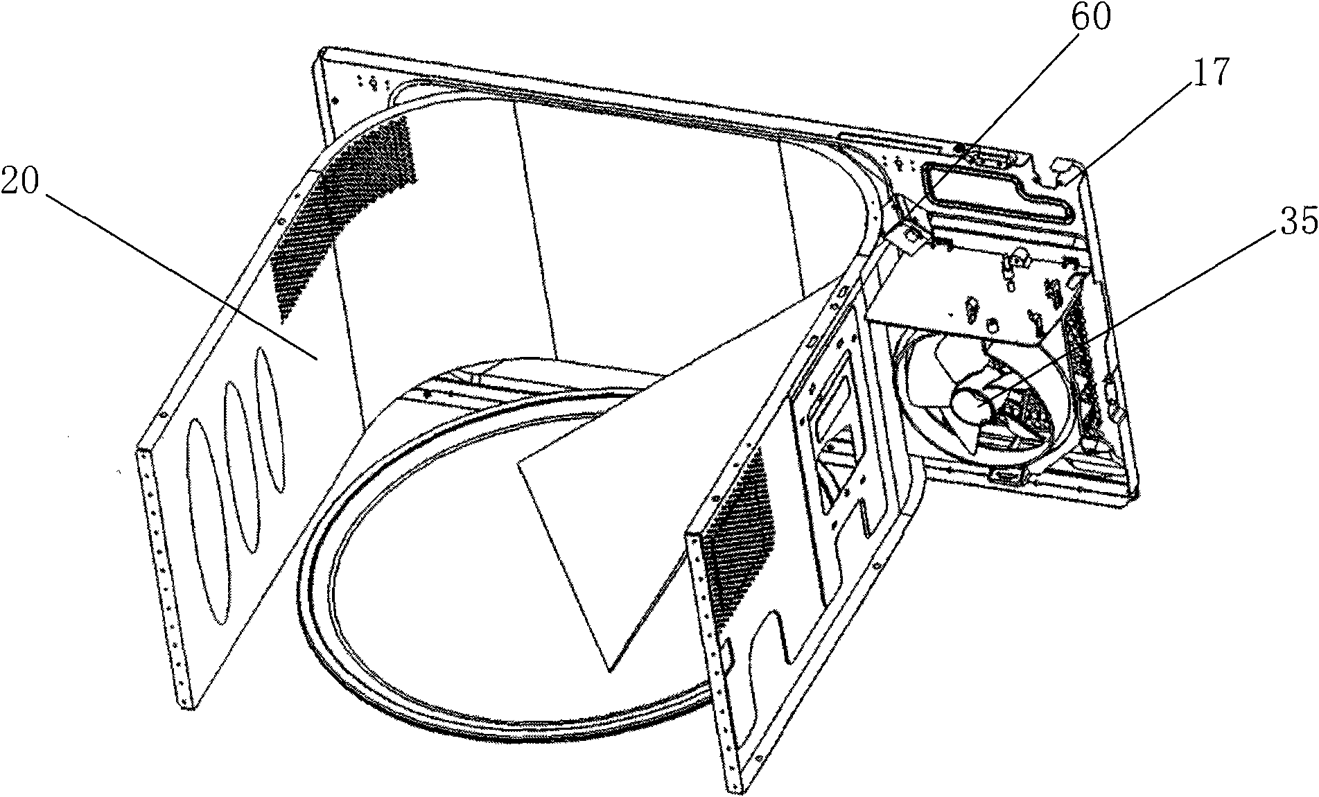
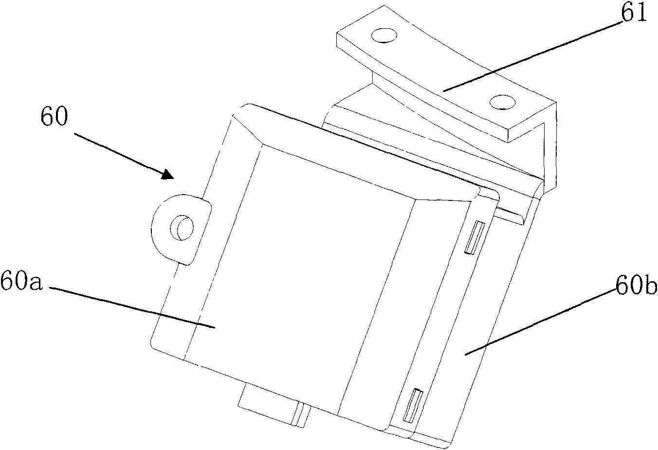
[0032] Figure 4 It is a structural schematic diagram of the sensor bracket in the sensor structure of the microwave oven of the present invention; Figure 5 It is a structural schematic diagram when the sensor bracket and the fixed frame are combined in the sensor structure of the microwave oven of the present invention; Figure 6 It is a structural schematic diagram when the sensor bracket is pulled out from the fixed frame in the sensor structure of the microwave oven of the present invention; Figure 7 It is a structural schematic diagram of the installation position of the fixing frame in the sensor structure of the microwave oven of the present invention; Figure 8 It is a schematic diagram of the rear panel of a microwave oven adopting the sensor structure of the present invention.

[0033] Such as Figure 4 to Figure 8As shown, the sensor structure of ...


PUM


Abstract

The invention discloses a sensor structure of a microwave oven. The sensor structure comprises a sensor probe, a sensor shell, a probe hole, a sensor bracket, a bracket through hole, a bracket baffle plate and a fixing rack, wherein the sensor bracket bears and fixes the sensor shell; the bracket through hole is formed on a back panel of the microwave oven; the sensor bracket can be inserted into and drawn out of the bracket through hole; the bracket baffle plate is arranged at the tail end of the sensor bracket to block the bracket through hole; the fixing rack is fixed inside the microwave oven; the position of the opening of the fixing rack corresponds to that of the bracket through hole; when the sensor bracket is inserted into the bracket through hole from the outer side of the microwave oven, the sensor bracket is inserted into and matched with the fixing rack inside the microwave oven; and when the sensor bracket is completely inserted, the position of the probe hole on the sensor shell corresponds to that of an observing hole on a furnace cavity. The sensor bracket can be taken out of the bracket through hole together with a sensor, after the sensor is cleaned outside the microwave oven, the sensor bracket and the sensor are inserted into the bracket through hole again and fixed, and therefore dirt on the sensor can be conveniently cleaned anytime.

Description

technical field [0001] The invention belongs to the technical field of microwave ovens, and specifically relates to a sensor structure of a microwave oven with a sensor that can be plugged and pulled from the rear panel of the microwave oven, so that dirt attached to the sensor probe can be cleaned at any time, and the sensor probe can be guaranteed to work correctly and normally. technical background [0002] A microwave oven is a device in which a magnetron generates microwaves after the power is turned on, and irradiates these microwaves on food and other heated objects to cook food. Such microwave ovens are classified into domestic microwave ovens equipped with small magnetrons and commercial microwave ovens equipped with large or multiple magnetrons. Microwave ovens can also be divided into household microwave ovens that generally use a glass turntable that rotates food, and commercial microwave ovens that mainly use a diffuser plate that irradiates microwaves. Commerc...

Claims


Application Information

Patent Timeline
Patent Type & Authority Applications(China)
IPC IPC(8): F24C7/08F24C7/02G01J5/00
Inventor 张国君方亚林彭飞
Owner LG ELECTRONICS (TIANJIN) APPLIANCES CO LTD
Learn More